Line diagram for kinnear door. Diagram 2 instr line lock sum 760000 102209 308 pm page 3.
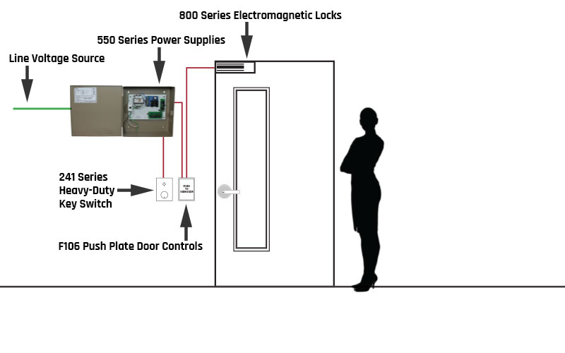
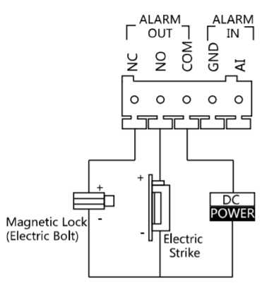
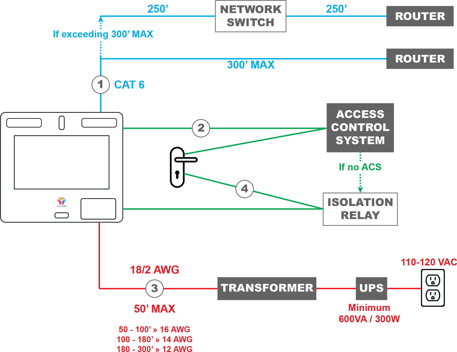
Access Control Wiring Diagram Help Deltrexusa
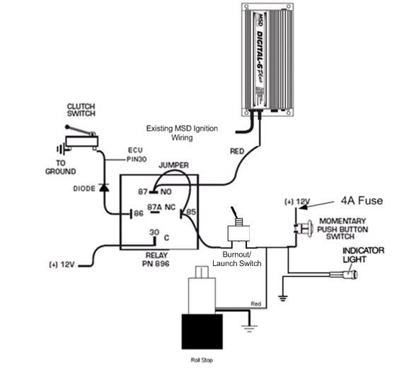
Line lock wiring diagram. 1 330 630 0240 monday through friday 9 am to 9 pm et. Everest d form. The red wire from the solenoid valve. Please choose a year from the menu at left to start your search. Mag lock wiring diagrams. The device is basically an electric solenoid controlled by a switch.
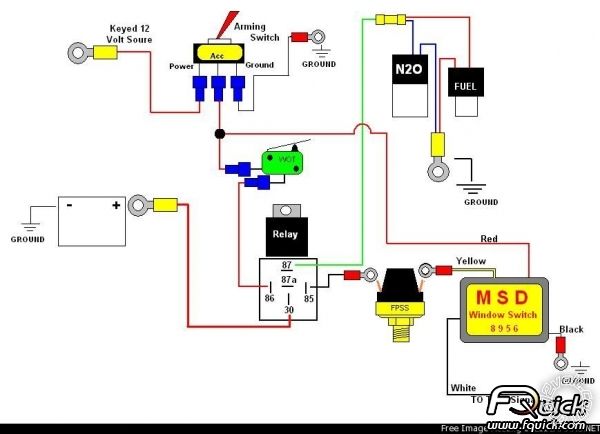
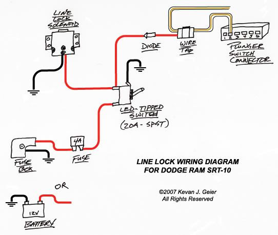
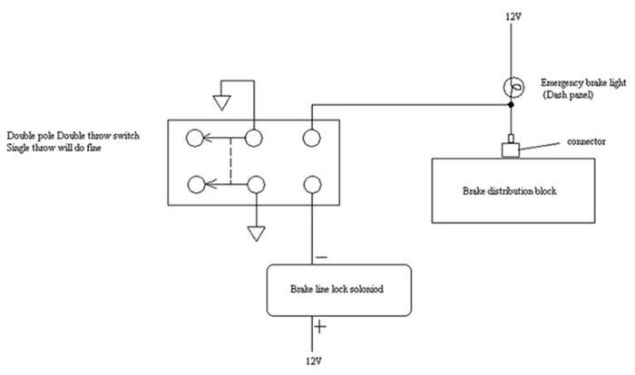
A snap lok fuse holder with 4 amp fuse is provided and should be incorporated into this wire. Reconnect battery and test for correct operation. Riser diagrams falcon exit devices. Common wiring diagrams. Below is a picture of my hurst line lock and a diagram of how i wired it. Brakes are now locked.
I disliked the large red bulb supplied with the hurst kit so i wired it to light the factory brake idiot light in the dash instrument cluster. Use at least a 22 gauge wire. I tapped the power at the parking brake switch and. Join the red wire from the lamp one of the wires from the switch either will work and the remaining black wire of the solenoid valve. Depress brake pedal and hold depress control switch and hold release brake pedal. One wire will be connected to solenoid red wire and the other wire black will be connected to the positive 12 volt system after the 4 amp fuse.
Make sure that the terminals of the micro switch are connected to the wires properly. Public restroom lock. All wiring connections should be soldered and covered with shrink sleeving. A line lock allows you to lock the front brakes independently of the rear brakes so the car stays put while the tires smolder. Schematics for concealed el devise. Lever locks for fire doors.
Steelcraft quote form. Chexit wiring diagram. Using a length of 18 gauge wire splice one end to the remaining wire of the switch and connect the other end to a switched positive terminal so that the brake lock is only operable with the ignition. Line lock wiring this site is best viewed in 1024x768 resolution. You will need to run two 2 wires from the micro switch. Wire per diagram on next page.
Welcome to winnebago industries wiring diagrams. Using a length of 18 gauge wire splice one end to the second wire of the switch and connect the other end to a switched positive terminal so that the brake lock is only operable with the ignition turned on.
Gallery of Line Lock Wiring Diagram


-8.png)