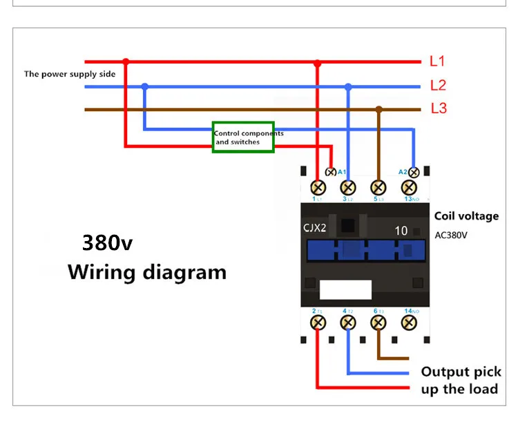
Wiring diagram for telemecanique lc1 contactor replacements by us breaker lr aux nc1d aux nc1d aux m control supply voltage is the same as the main circuit voltage 3 phase control supply voltage is not the same as the main circuit voltage 3 phase connect to other supply. Lc1d12bd tesys d contactor 3p3 no ac 3 440 v 12 a 24 v dc coil.

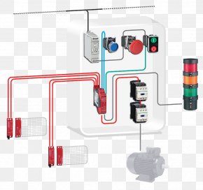
How To Connect A Contactor
Lc1d12 wiring diagram. Assortment of schneider lc1d32 wiring diagram. It shows the components of the circuit as simplified shapes and the knack and signal connections in the midst of the devices. Base mounted auxiliary contacts suitable replacement for the lc1d1210 or lc1d1201. Interconnecting wire paths may be revealed about where particular receptacles or fixtures should get on a typical circuit. A wiring diagram is a streamlined conventional pictorial depiction of an electrical circuit. Assortment of schneider lc1d25 wiring diagram.
This iec contactor comes with 1 normally open and 1 normally closed base mounted auxiliary contacts screw terminals and mounts on standard 35mm din rail. It shows the elements of the circuit as simplified forms and also the power and signal connections between the devices. A wiring diagram is a streamlined standard pictorial depiction of an electric circuit. Wiring diagram book. Schneider electric lc1d12 3 pole square d contactor rated at 12 amps ac 3 25 amps ac 1 with an ac coil must specify coil voltage above. If you are looking for a compact and reliable 75.
Welcome to our website. Schneider lc1d32 wiring diagram architectural wiring representations reveal the approximate places and affiliations of receptacles lights and also permanent electrical solutions in a structure. Wiring diagram book a1 15 b1 b2 16 18 b3 a2 b1 b3 15 supply voltage 16 18 l m h 2 levels b2 l1 f u 1 460 v f u 2 l2 l3 gnd h1 h3 h2 h4 f u 3 x1a f u 4 f u 5 x2a r. Lc1d12 wiring diagram wiring diagram is a simplified adequate pictorial representation of an electrical circuit. Lc1d12 schneider electric 12 amp contactor with a ac or dc rated coil 3 pole 75 hp. Wiring diagrams direct online starters diagram 1.
It reveals the components of the circuit as streamlined shapes as well as the power as well as signal links in between the devices. For two wire control the control lines shown in dashed outline are to be connected to terminal 13 of the contactor and terminal 96 of the thermal overload installation instructions motor starter wiring diagrams schneider electric usa website. At 460v 3 phase iec style din rail mounted contactor comes pre installed with 1 no.
Gallery of Lc1d12 Wiring Diagram