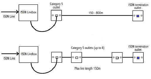
Usually this is the case when an isdn line is provided from a phone system. In the first diagram a cat 5 outlet is used with a cat 5 patch cord as a simple way to connect the extension wiring to the linebox.
Isdn A Basic Guide
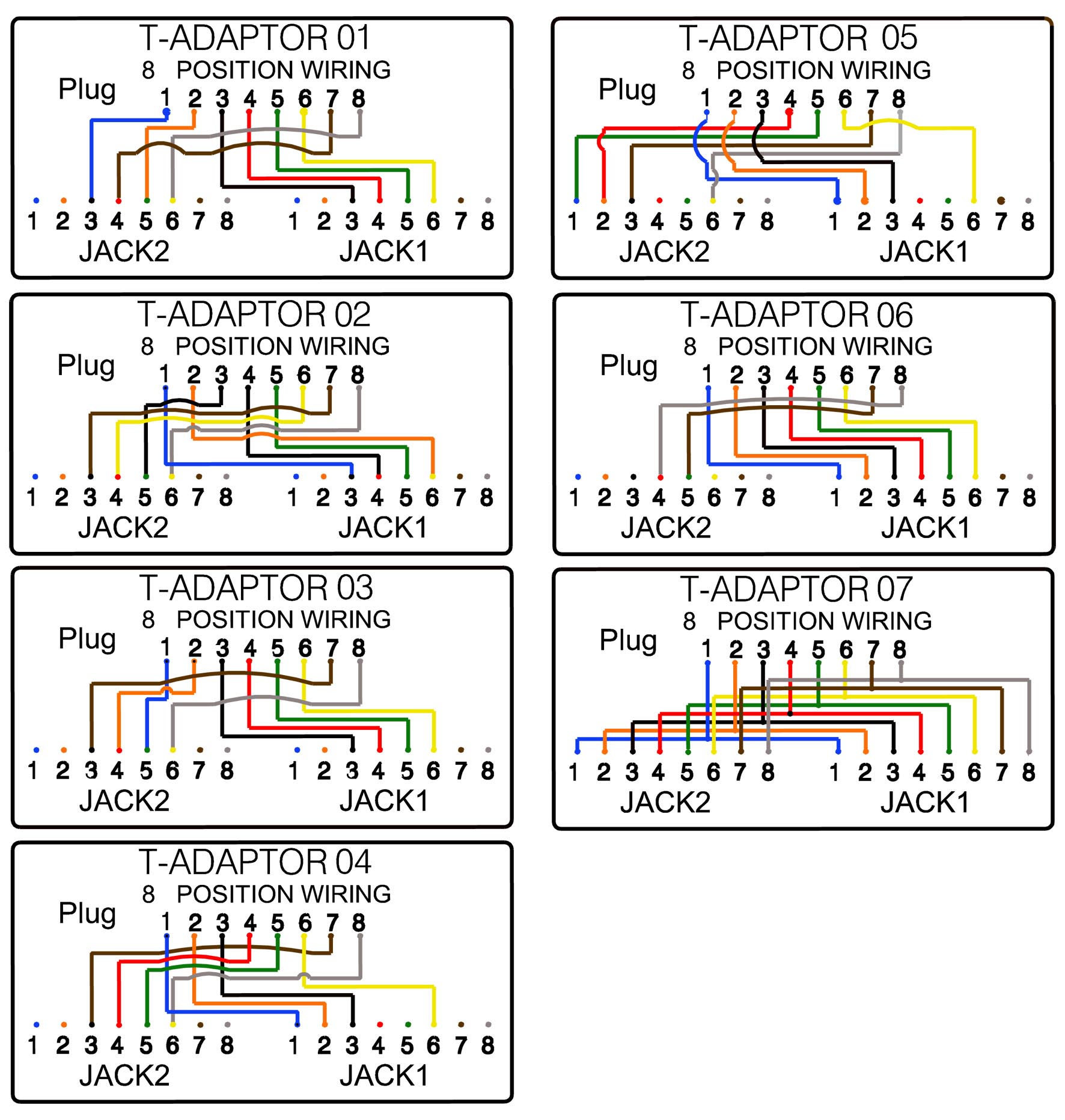
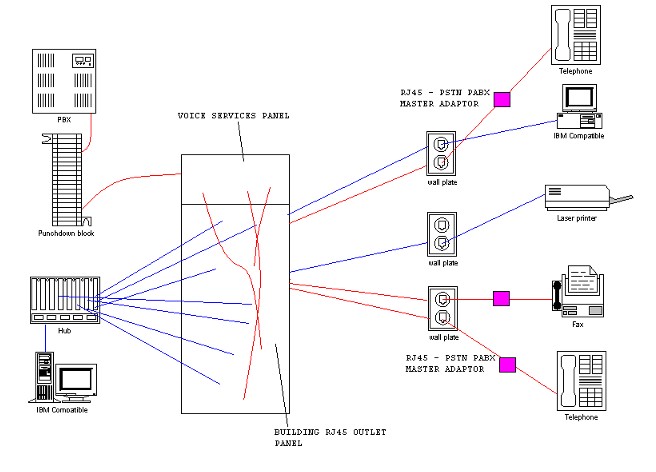
Isdn wiring diagram. In the second diagram cat 5 outlets are daisy chained from the linebox. These can also be used for network 10base t cabling. A distribution box can be used to help organize the wiring when wiring a homeoffice with a pabx as each extension has to be wired back to one point. The above diagram shows an ethernet crossover cable pin out for reference. Att 555 021 101 issue 3 february 1993 isdn installation and test manual b b 1 1993 att. Should you need to make one of these cables up please use the diagram below as a reference.
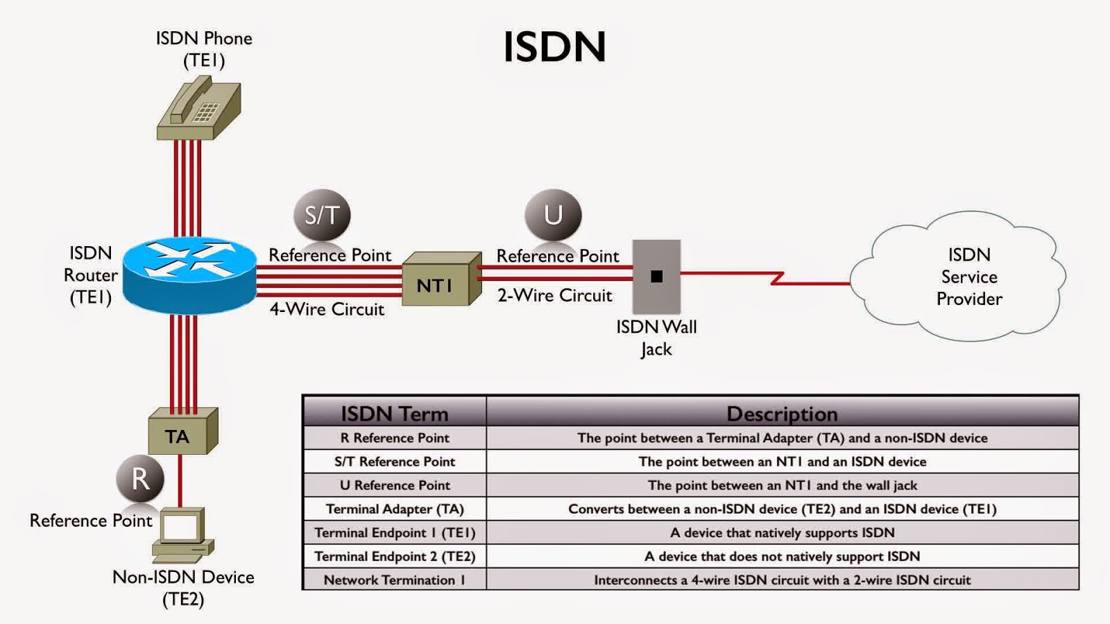
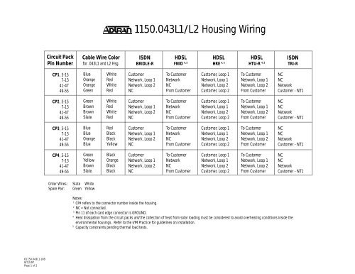
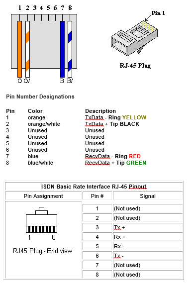
To the isdn termination jack. Cat5 cable is color coded in pairs and each pair consists of two wires twisted together within the cable. The two interfaces shown are bri and pri. The digital channels for the bri are carried over a single unshielded twisted pair of copper wires and the pri is normally carried on 2 twisted pairs of copper wire. As there is only one socket on the extension wiring this may extend as far as 800m. However for network cabling cat5 is recommended.
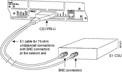
Normal telephone cable is used for isdn or telephone sockets and can be used for networking. Do not use an ethernet or network crossover cable as these are different to an isdn crossover cable. Wiring up isdn cable. This diagram shows the different interfaces that are available in the integrated services digital network isdn. Standard cat5 utp unscreened twisted pair cable is recommended for all types of telephone station wiring and should always be used for isdn cabling applications.
Gallery of Isdn Wiring Diagram