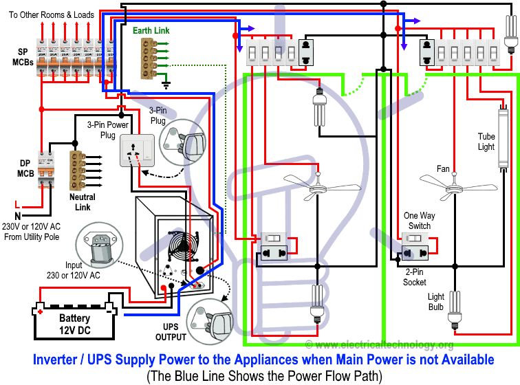
Automatic ups system wiring diagram in case of some items depends on ups and rest depends on main power at office or home. Then connect the white or other neutral wire to the neutral bus.
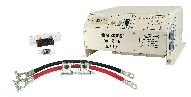
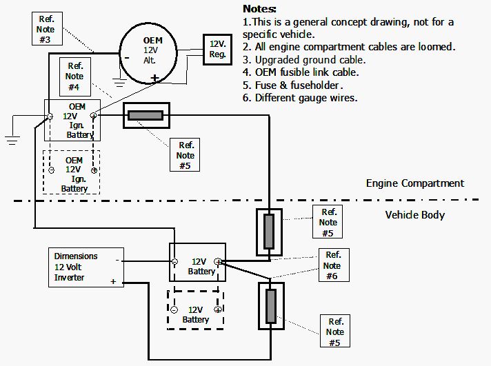
Power Inverter Installation Magnum Dimensions
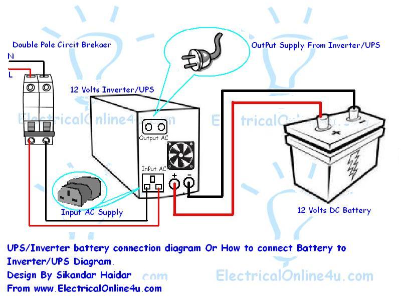
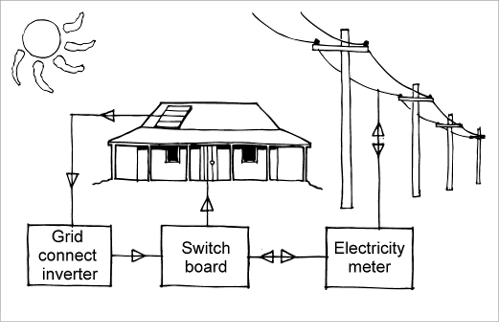
Inverter connection in house wiring diagram. According to your requirement connect the load to the inverter. Start with professional wiring diagram software can produce top quality wiring diagrams with a shorter time. Wiring the inverter to the breaker panel. An inverter is connected to the battery. Circuit diagram of house wiring with inverter. The primary function of an inverter is to convert direct current dc power into standard alternating current ac this is because whereas ac is the power supplied to industry and homes by the main.
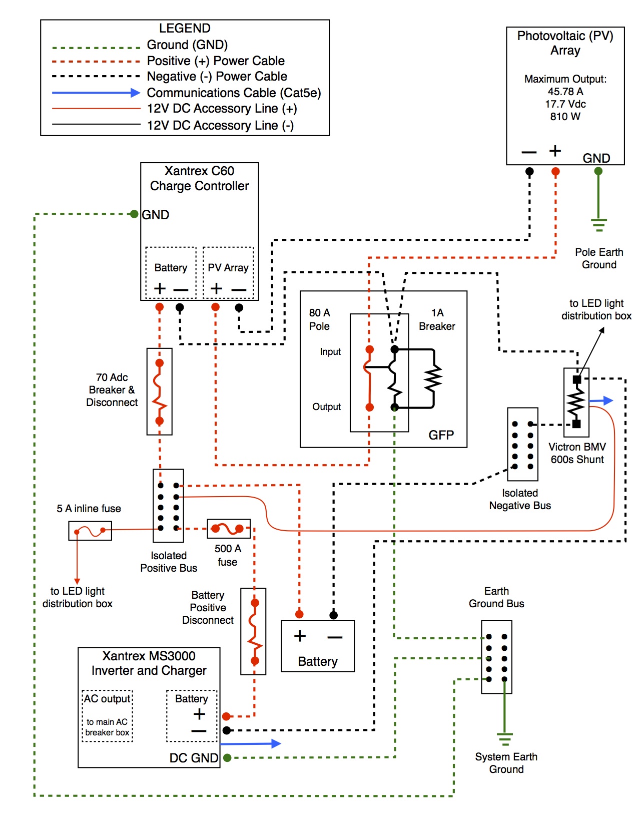
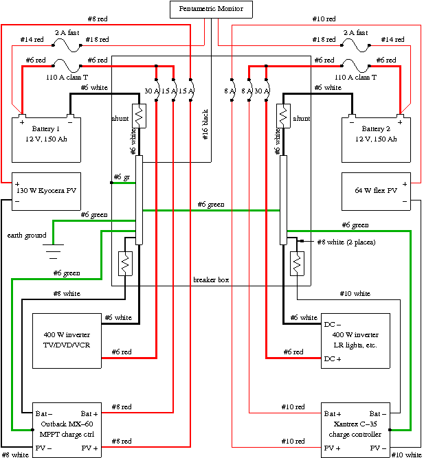
Related electrical wiring tutorial. The size of the wiring will depend on the maximum anticipated amperage of the system along with its voltage. Manual ups wiring diagram with change over switch system. How to wire solar panel to 220 v inverter 12v battery 12vdc load and 220v ac load220v fan light etc ac dc load. Now according to the below ups connection diagram connect an extra wire phase to those appliances where we have already connected phase and neutral wires from power house db ie two wire as phase live as shown in the below fig. Now youre ready to wire the inverter to the breaker.
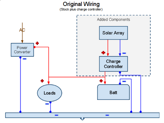
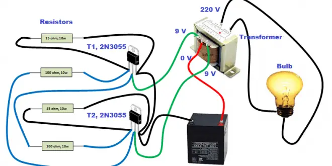
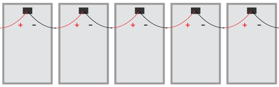
Manual circuit diagram of house wiring with inverter a close anaylsis on the works along with what doesnt. Thanks for the read and watch the video. Ups inverter wiring diagram with auto manual changeover switch system. As you see in the connection diagram at first the solar panel is connected to the solar charge controller and then a 24v battery is connected to the charge controller. A 12 v car battery can be used as the 12v. Wiring diagram of solar panel with battery inverter charge controller and loads.
The circuit diagram for an inverter connection at home is given below. Make sure that the inverter is capable according to the manufacturer of being connected to a circuit breaker panel. It shows how the electrical wires are interconnected and can also show where fixtures and components may be connected to the system. The usual aspects in a wiring diagram are ground power supply cable as well as connection result tools buttons resistors reasoning gateway lights etc. Remove the cover for an unused circuit breaker and punch out the hole. First the black wire then the red wire to the corresponding terminals.
Inverter connection diagram in home home wiring diagram. The output of the inverter is connected to ac loads like fans lights tv etc. Connect wiring to the output from the power inverter. To read a wiring diagram initially you need to know just what essential aspects are consisted of in a wiring diagram and which pictorial symbols are made use of to represent them. A wiring diagram is a simple visual representation of the physical connections and physical layout of an electrical system or circuit. According to the below circuit diagram you can see that during load shedding light 3 fan and tv can be run by the inverter.
Gallery of Inverter Connection In House Wiring Diagram