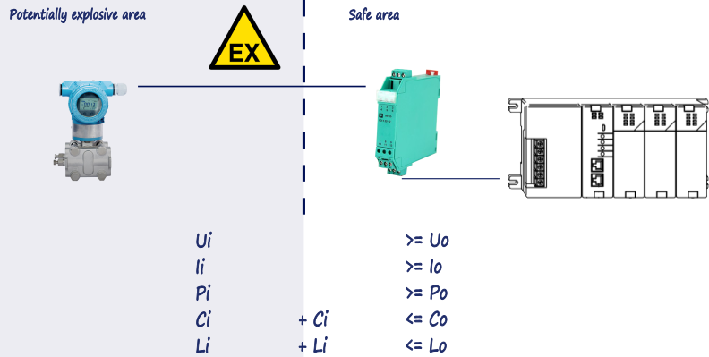
Examples of simple devices are contacts thermocouples and rtds. All io is passed through the intrinsic safety barriers.

Utilizing Intrinsic Safety Techniques For Controlling
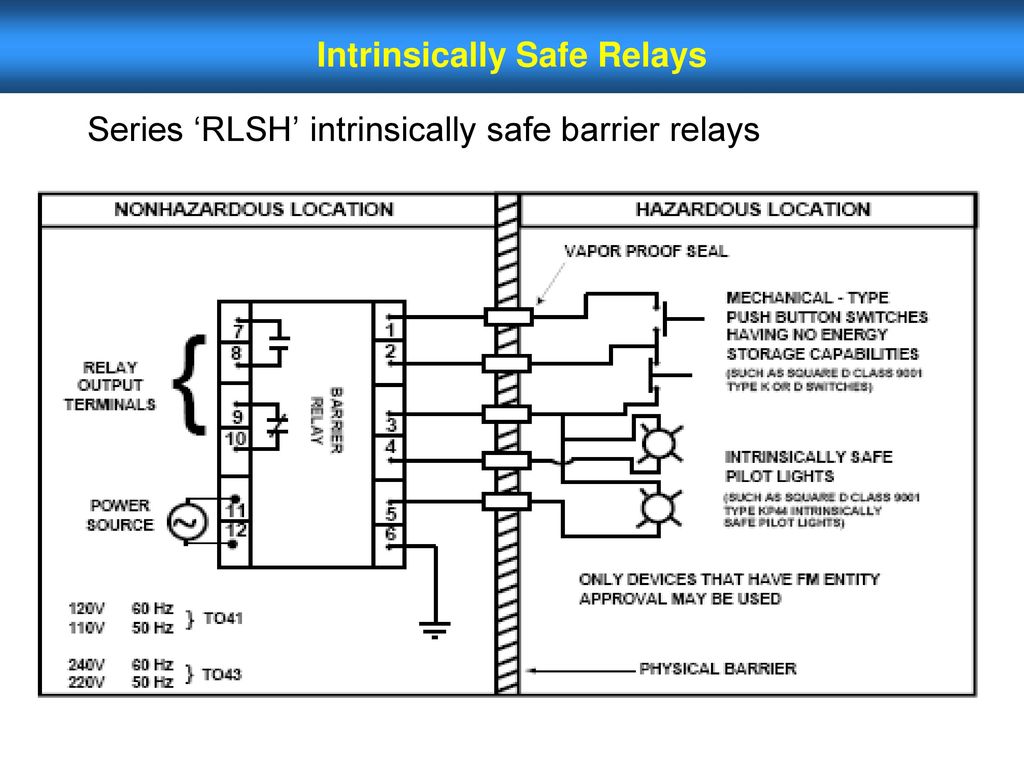
Intrinsically safe barrier wiring diagram. The basic components that make up most intrinsic safety barriers are a fuse zener diodes and a resistor and are shown below in this simple electrical diagram. It shows the components of the circuit as streamlined shapes and the power and signal connections in between the tools. Intrinsically safe barrier wiring diagram building wiring representations reveal the approximate places as well as affiliations of receptacles illumination and permanent electrical services in a structure. If the field device does create or store energy that exceeds 12v 01a or 25mw then it is considered a non simple device. They render non voltage producing sensors intrinsically safe for operation in potentially hazardous areas. A wiring diagram is a streamlined conventional pictorial depiction of an electrical circuit.
They can be connected with any device having a dry contact limit switch magnetic switch. A wiring diagram is a streamlined standard photographic representation of an electrical circuit. Intrinsically safe barrier wiring diagram electrical earth loop to structure steel by a 70 mmsq cable in general used the earth bus bar is made from copper and has 1 ½ width and ¼ height. It shows the parts of the circuit as simplified forms as well as the power and signal connections between the tools. Intrinsically safe barrier wiring diagram download variety of intrinsically safe barrier wiring diagram. Adjoining cord paths could be revealed roughly where particular receptacles or fixtures have to be on a common circuit.
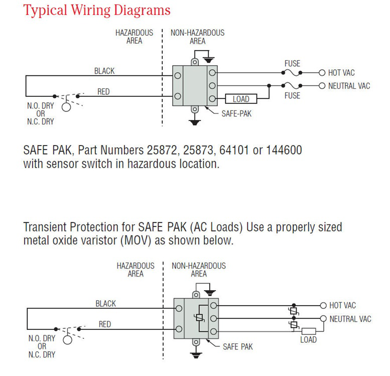
Gallery of intrinsically safe barrier wiring diagram download variety of intrinsically safe barrier wiring diagram. Learn more about programmable electronic safe pak relay. The circuit or instrument in the hazardous area operates normally until a fault condition occurs. Wellborn assortment of intrinsically safe barrier wiring diagram. The answer to that question lies in the definition of intrinsically safe. It reveals the elements of the circuit as streamlined shapes and also the power as well as signal links in between the gadgets.
Request technical help 1 cowles road plainville ct 06062. Therefore the simple device is connected to the intrinsically safe barrier through the field wiring. The is isolators are the green modules that are lit up. Wires from these modules pass through the duct with the blue cover photo courtesy of phoenix contact inc. Wiring diagram images detail. Relays barriers wiring diagrams.
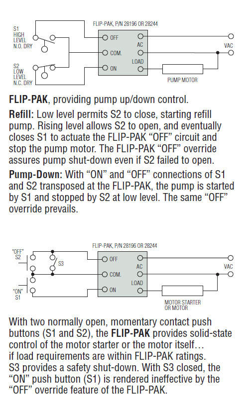
A wiring diagram is a simplified standard photographic representation of an electrical circuit. Examples of non simple devices are transmitters. Intrinsically safe relays such as the ny2 and the class 8501 type to relays act as an energy barrier limiting the voltage an d current available in the hazardous area. October 23 2018 by larry a.
Gallery of Intrinsically Safe Barrier Wiring Diagram