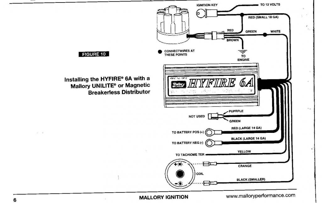
Mallory hyfire 6a wiring diagram note. ł connect the long black wire to engine ground or chassis ground.
Wrg 0526 Renault Megane Wiring Diagram Engine
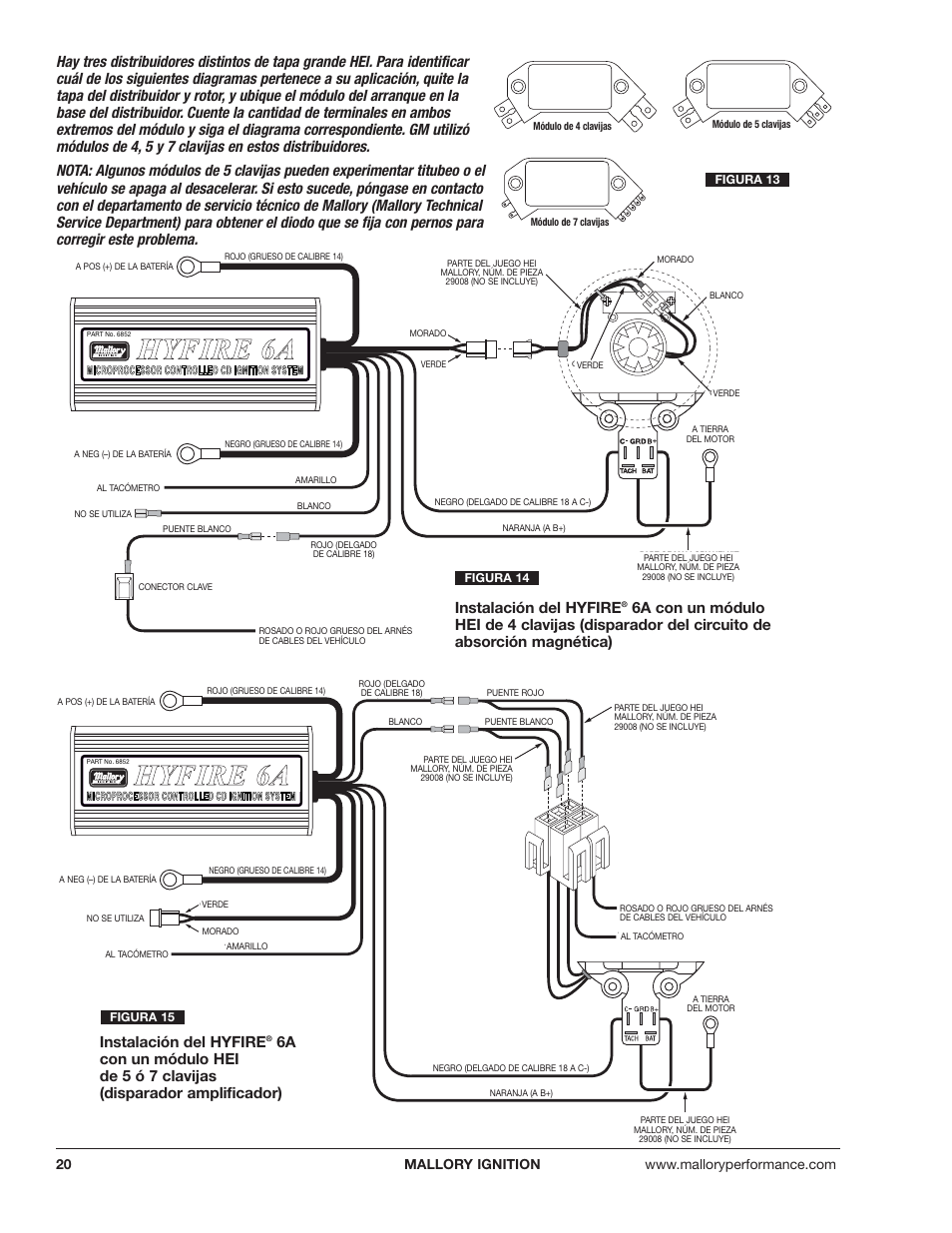
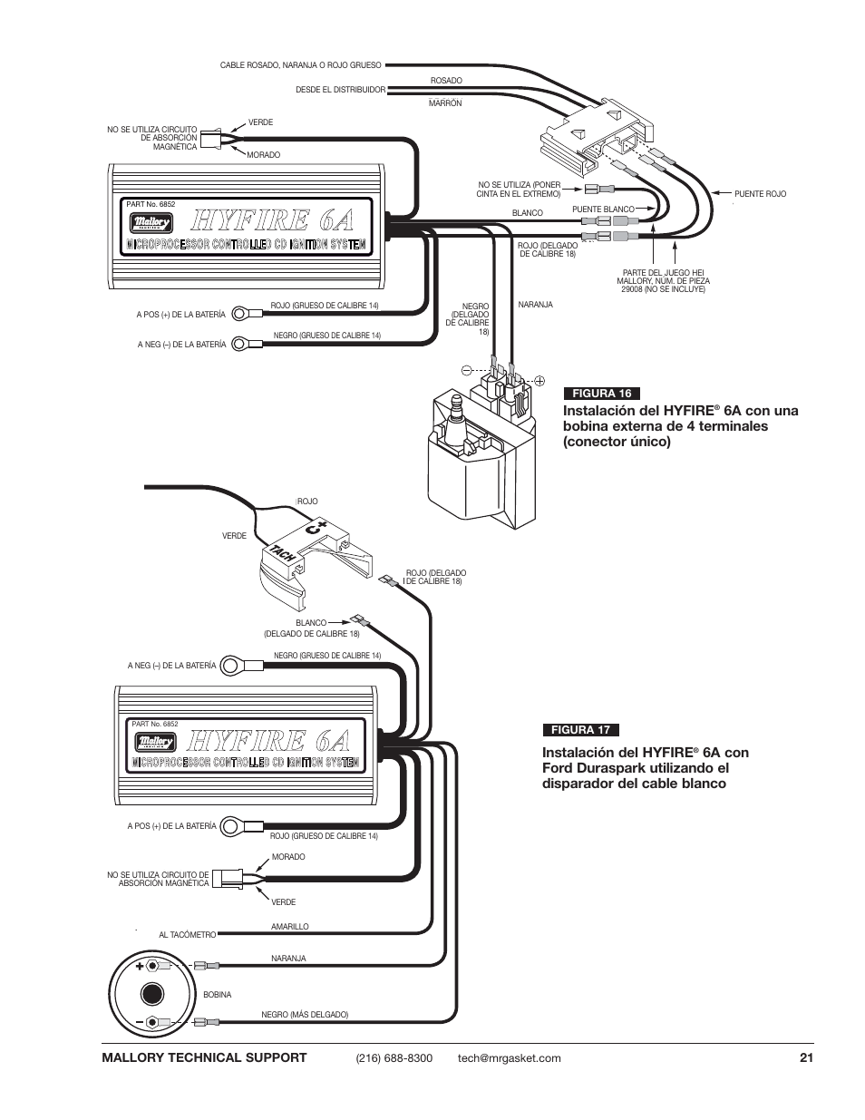
Hyfire 6a wiring diagram. Of terminals on both ends of the module and follow the corresponding diagram. The system has an impressive track record and can boast the largest reference list of any en54 compliant hybrid system available today. ł connect the long black wire to engine ground or chassis ground. Do not use mallory s pomaste coil pn tachometers the yellow wire on note. Recommend mallorys promaster coil pn or mallorys all of the wires of the hyfire. Spark plugs and wires high quality spiral wound wire and proper routing are essential to the operation of the hyfire 6a ignition controlthis type of wire.
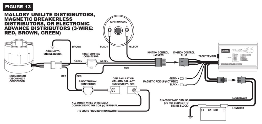
Figure 1 unilite wiring diagram using ballast resistor note. Do not install the hyfire 6a ignition control in any vehicle that is originally equipped with a cd ignition control. Hyfire 6a ignition control. If your vehicle is equipped with a hyfire. Wiring layouts are comprised of two things. Do not use solid core spark plug wires with the hyfie 6a ignition.
ł connect the long red wire to the battery post or battery terminal on the starter solenoid. Like the 6a box the 6al has a primary voltage of 520 540 volts and secondary of 45000. Mallory 6a 6al and msdtm 6 series ignition. The hyfire range of products is the most technically advanced and innovative hybrid fire solution available in the uk. 10 gauge or larger is required. The on board soft touch rev control is one of the main differences between the 6a and 6al.
Locate one long red wire and one long black wire at the end plate of the hyfirefi iv electronic ignition control. ł connect the long red wire to the battery post or battery terminal on the starter solenoid. ł plug into 2 pin connector with red and black wires coming from the end plate on the. Long black wire at the end plate of the hyfirefi vi electronic ignition control. This means no external rpm modules to plug in anymore simply adjust the rotary dials located on top and you are ready to go. The purpose of an ignition ballast resistor between the ignition switch 12v and the ignition coil positive.
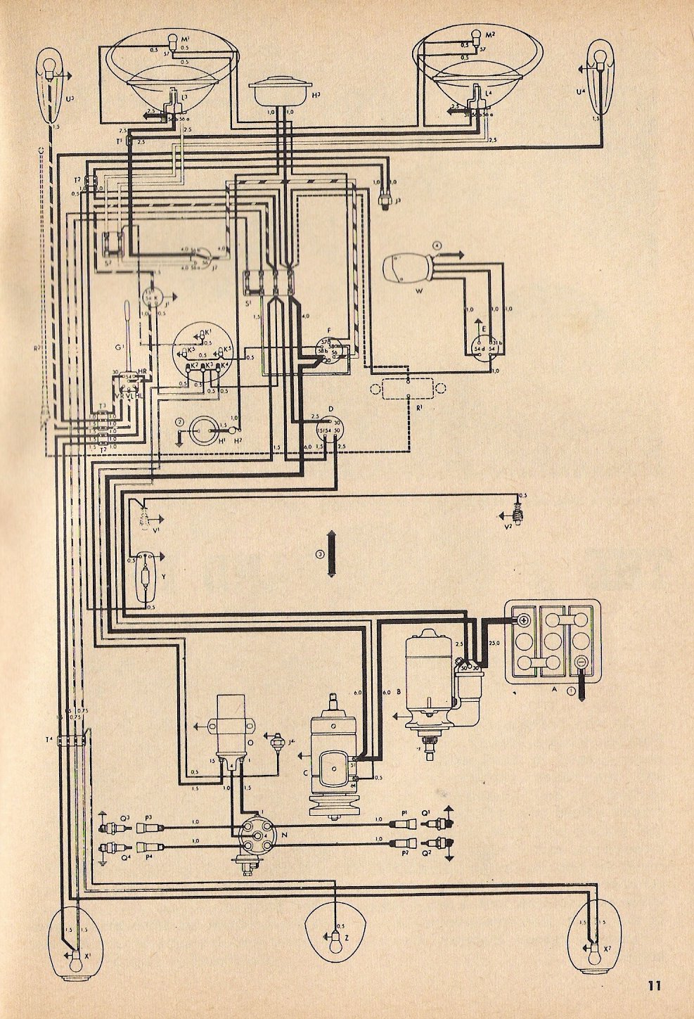
Hhy yf fiir re e 6 6a a mallory ignition wiring diagram 2 lenito at wellread wiring just whats wiring diagram. Symbols that stand for the parts in the. A wiring diagram is a sort of schematic which makes use of abstract photographic icons to reveal all the affiliations of components in a system.
Gallery of Hyfire 6a Wiring Diagram