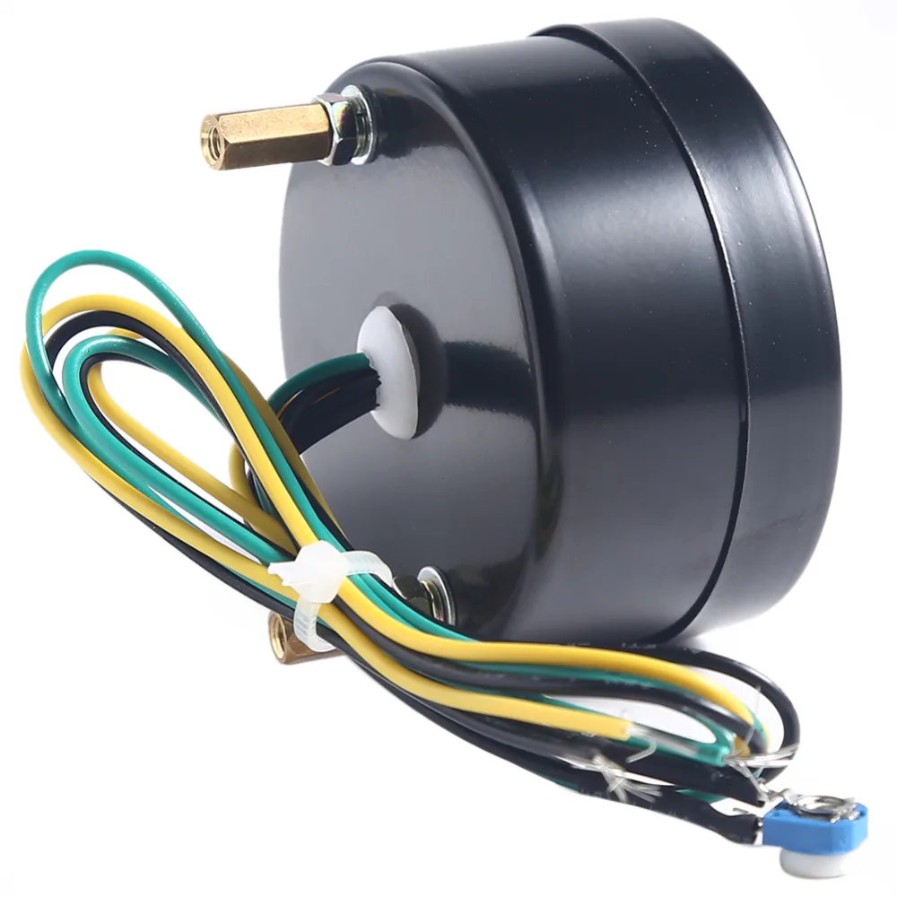
S for the sender g or for the ground and i for the ignition. See diagram on the next page for connections standard case 3.
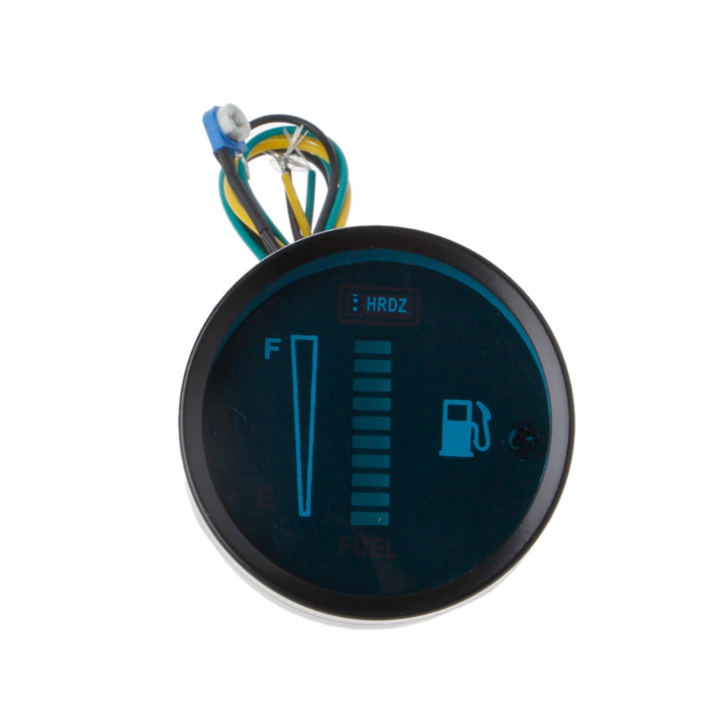
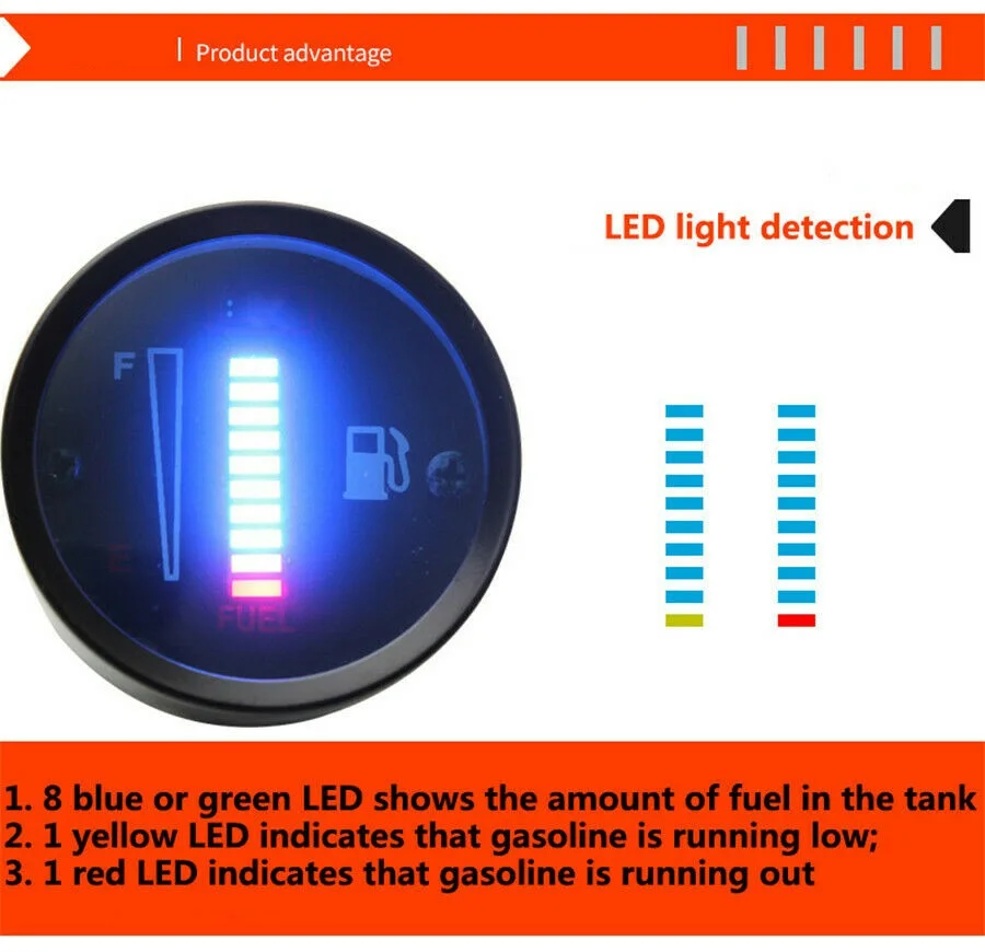
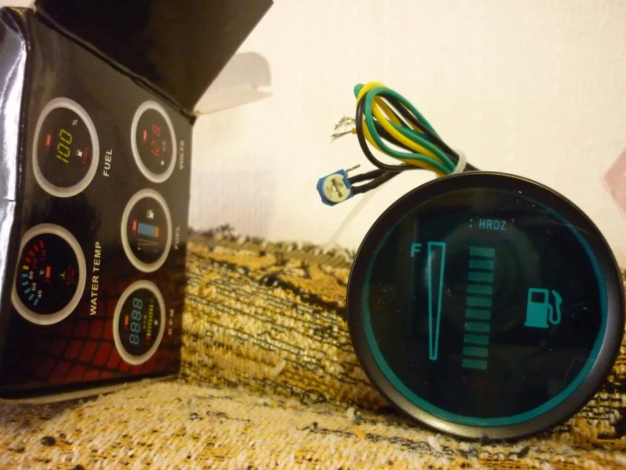
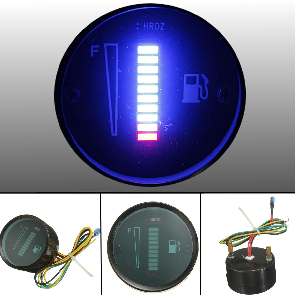
Led Fuel Gauge
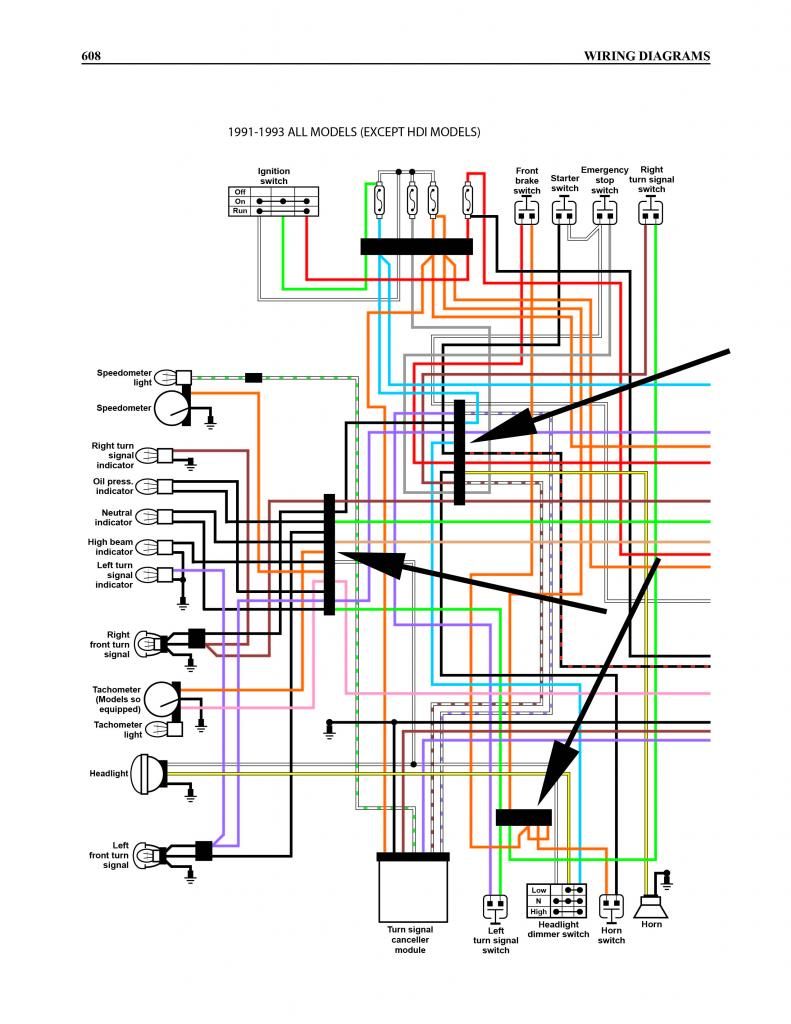
Hrdz fuel gauge wiring diagram. Obtain 12 volt power from the fuse box using a standard wire and connect it to the positive terminal of the fuel gauge. All the wires at the connectors have alphanumeric addresses showing where the other end of the wire is located ac cording to the grid. Next connect a wire from the float on the fuel tank to the negative terminal of the fuel gauge. Step 2 connect the end of the wire to a bare metal surface on the vehicle. Removing the sending unit wire from the chassis ground the fuel gauge should go directly to full. Fuel gauge sending unit wiring diagram collections of 36 fuel gauge wiring diagram chevy types of diagram.
The fuel gauge should immediately go to empty. Next check the fuel tank float assembly to see if the grounding terminal on the float assembly has a good grounding point to the chassis. It is recommended that insulated wire terminals preferably ring type be used on all. Automotive wiring diagram worksheet inspirationa fuel gauge sending. Wiring diagrams description these diagrams use a new format. Check the wiring diagram that comes with the kit and mark the back of the new fuel gauge with symbols for each post.
If the fuel gauge responds correctly the fuel gauge and sending unit wire at this point are reacting correctly. How to wire fuel gauge and sending unit complete explanation old crows classic cars. Wire a fuel gauge by first disconnecting the old dysfunctional unit to replace it with a new one. Since the gauge gets its ground by being bolted into the instrument panel you need to either crimp on a small ring terminal to this ground wire going to the battery negative terminal and then nut and bolt this to the fuel gauges housing or if not come up with a way to attach this wire solidly to the gauges housing. Super easy boat wiring and electrical diagrams step by step tutorial duration. Install the new gauge reconnect the wiring and turn on the power.
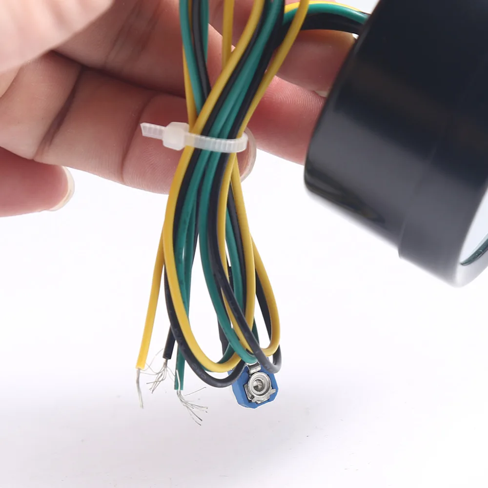
Connect opposite end to the fuel level senders signal wire or terminal. The diagram is surrounded by a alphanumeric loaction grid. Connect a wire to the gauge stud marked s signal and secure with nut and lock washer. The fuel gauge should now show the correct fuel level in. Electric fuel sender wiring diagram wire center wiring diagram. The connectors are shown with end on views with.
Fuel sending unit wiring diagram volovetsfo. These will be labeled s for the fuel sender signal wire for the 12v positive wire for the 12v negative wire and the last will be the gauge light power wire.
Gallery of Hrdz Fuel Gauge Wiring Diagram