Red now there can be two separate wires for this. Again referring to the honeywell thermostat ct31a1003 wiring diagram you can see it requires only two wires r and w.

Km 6175 Wiring Honeywell Thermostat Pro 4000 Wiring Circuit
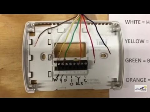
Honeywell thermostat wiring diagram. Metal jumper for thermostat rc and rh terminals. Use our helpful tool to take an assessment of the existing wiring in your home. C 24 vac common you might see blue purple or brown typically used for this wire. White the white wire is what connects to the auxiliary heat on your system. If not the arrangement wont function as it should be. Honeywell thermostat wiring diagram 4 wire examples the table above provides a more complete list of honeywell thermostat wiring colors and their uses.
Our wiring diagrams section details a selection of key wiring diagrams focused around typical sundial s and y plans. Thermostat wiring and wire color chart thermostat wiring colors code. Green the green wire connects to the fan. It doesnt control cooling and because its a mechanical thermostat it doesnt need power for internal functions so it has no c wire. The honeywell home trademark is used under license from honeywell international inc. Use our helpful tool to take an assessment of the existing wiring in your home.
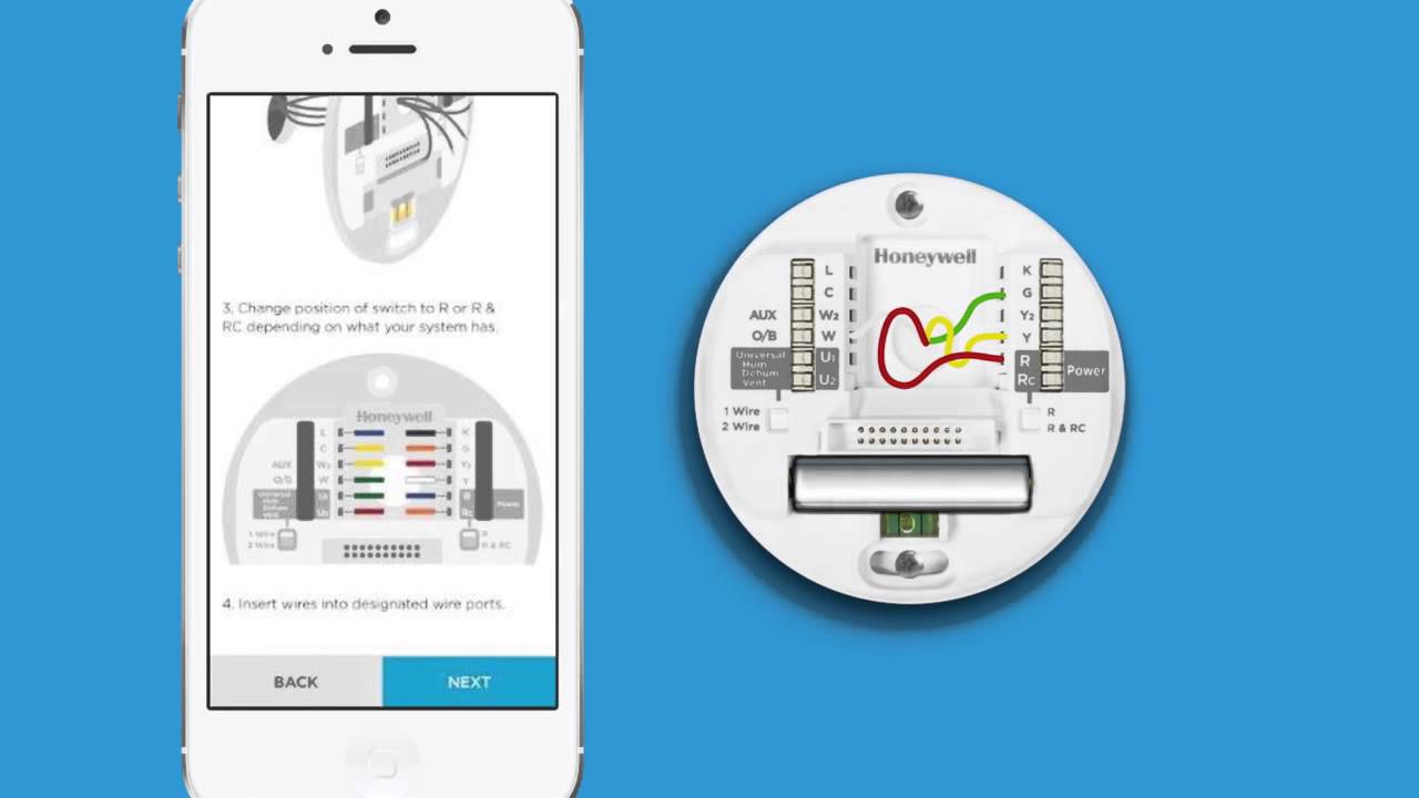
Honeywell wifi thermostat wiring diagram honeywell lyric t5 wi fi thermostat wiring diagram honeywell smart thermostat wiring diagram honeywell t5 wifi thermostat wiring diagram every electric arrangement is made up of various distinct parts. Orange this wire connects to your heat pump if you have one. Furthermore this thermostat wiring diagram is specifically for a system with two transformers. That is a basic honeywell thermostat wiring diagram for a single stage heat pump. It is a red wire and comes from the transformer usually located in the air handler for split systems but you may find the transformer in the condensing unit. But here is a list of the most common wire color mappings as seen in many four wire t stat setups.
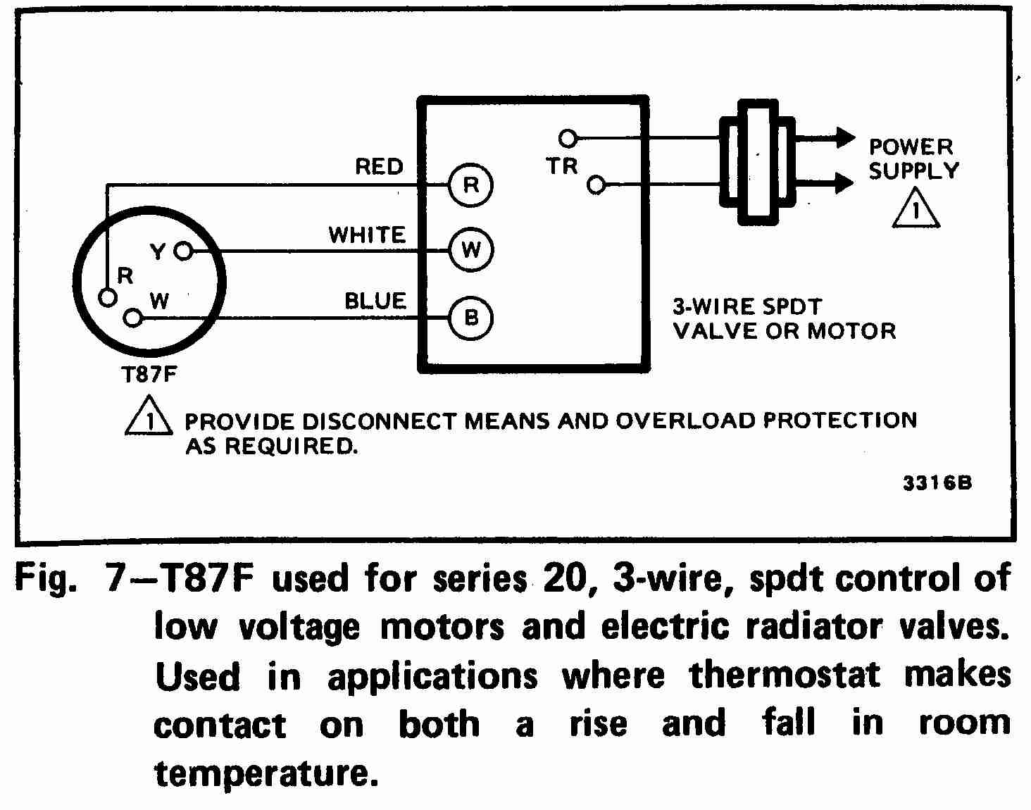
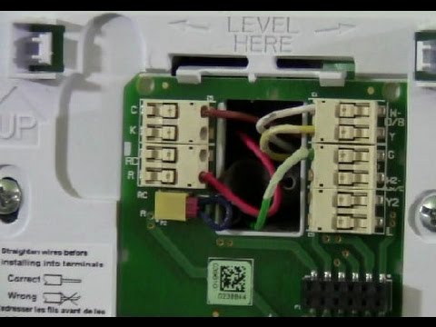
Keep in mind that there should be a low voltage cable in the wall where the thermostat is located which has individual wires as shown in the instructions below. If you have a two stage heat pump then you will also utilize terminal y2 for the second stage. Yellow the yellow wire connects to your compressor. Learn more about resideos response to covid 19. R the r terminal is the power. At left the thermostat wiring diagram illustrates use of a honeywell t87f thermostat in a 3 wire application as a spdt single pole double throw switch such as used to control low voltage motors electric radiator valves zone valves.
The model number of the honeywell thermostat was not provided however here are the typical wiring assignments for a conventional heating system. Each component should be set and connected with different parts in specific manner. Color of wire and termination. Find out if your home is compatible with a honeywell home thermostat.
Gallery of Honeywell Thermostat Wiring Diagram