The amount of volts sent to the led driver tells it how bright to be. Replace wiring access cover securely tighten cover.

High Bay Light Wiring Diagram Diagram Base Website Wiring
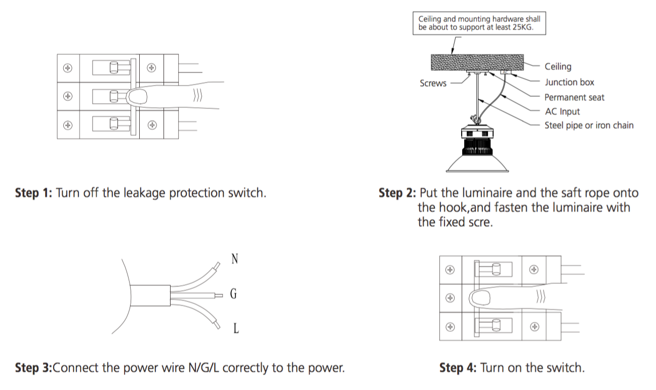
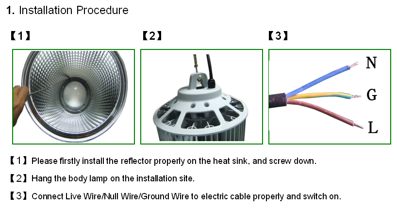
High bay lighting wiring diagram. 4 ºf to 131ºf 0 10v dimming control this light source is not intended as an. Industrial high bay led luminaires installation maintenance information. Send 0 volts and the light is off. Installation should be performed by a qualified electrician or installer. L brown n blue green yellow please make sure the power off before opertion warning hammer expansion screw 850mm or 315 in takes off the nut after expansion screws are. These instructions can be used to install eco linear high bays.
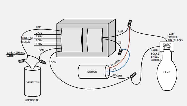
Pull field wiring into mounting bracket. Aurora ohio 44202 p. Read all precautions warnings instructions contained in this document. 120vac to 277vac operating temperature range. Connect green ground from power supply to green ground in housing and secure with wire nut wiring instructions 325 campus dr. Connect supply wires to luminaire wire leads per the wiring diagram using methods that comply with all applicable codes.
Zero to ten volt stylized as 0 10v is actually one of the earliest signaling system invented for lighting control and is also one of the simplest. The accuracy or completeness thereof is not guaranteed. Connect red wire from power supply to blue or red lead and secure with wire nut. Send 10 volts and the light will go to maximum power. Then light up the lamp must be installed by a licenced electrician as per the latest as 3000 wiring regulations ufo led high bay installation manual cable ac 100 277v note. It uses a control signal of low voltage that ranges from 0 to up to a maximum 10 volts.
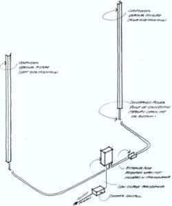
In accordance with dialight terms and conditions of sale and. Vigilant led high bay luminaire for industrial areas wiring diagram all statements technical information and recommendations contained herein are based on information and tests that dialight believes to be reliable.
Gallery of High Bay Lighting Wiring Diagram