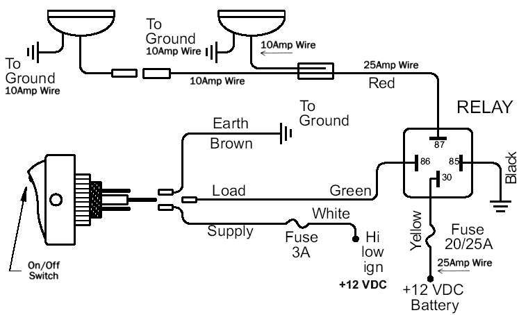
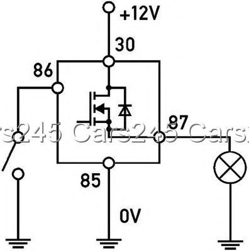
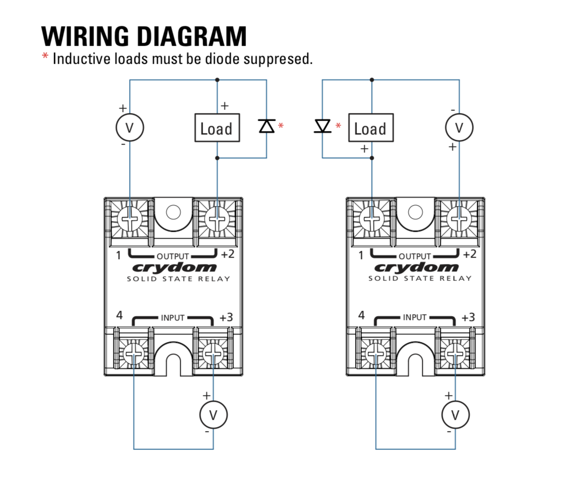
May 12 the part number on the relay is 4rd this is the german hella part number. When using a solid state relay to control a device that may have significant fly back voltage such as most solenoids lpe recommends connecting a transient voltage suppression tvs diode across the device.

Hella Wiring Diagram Wiring Diagram
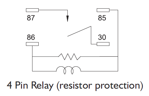
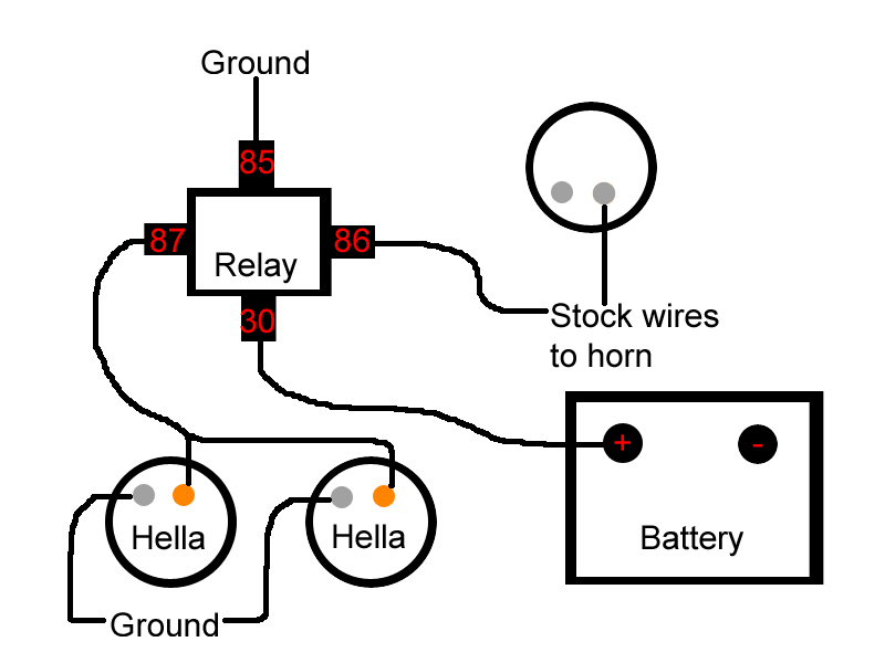
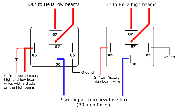
Hella 4ra relay wiring diagram. Current controlled relay for direction indicator lamps bi stable relay for switching between low and high beam. Simple relay switch wiring could you advise with the wiring of a relay hella 4ra as the technicals explain but skip over the switch placement. Can you tell me simply the configuration to wire a relay especially how a switch is wired to the relay i think with the option to place befhella supertone horns archive. Mechanical threshold voltage controller for windshield wipers 1965 e relay. Four pin relays do not use this terminal see reference 2 under the common pin designations chart. The first fully electronic flasher unit 1968 l relay.
Relays hella relay product range hella solid state relay hella home page catalog hella relays electrics catalog hella hella 4ra 965 400 001 relais arbeitsstrom 12v mit homepage hella lighting catalog hella homepage hella my hella lights wiring harnesses pigtails. Solenoids and the hella relay is well suited to these applications. 4 5 1951 first hot wire flasher unit 1960 a relay with metal housing. Commercial vehicle application chart. Determine which wire leads to the second electrical device if equipped. Slide this wires wire terminal onto a hella five pin relays terminal labeled 87a this terminal turns hot when the control circuit deactivates.
This wiring configuration can be seen in the adjacent wiring diagram. The first modular system 1969 wipewash interval control unit 1970 k relay. 4rd as but base plate without ventilation hole 4rd hl hella 12v 1020a mini relay spdt with resistor high temperature hl hella 12v 1020a mini relay spdt with resistor high temperature javascript seems to.
Gallery of Hella 4ra Relay Wiring Diagram