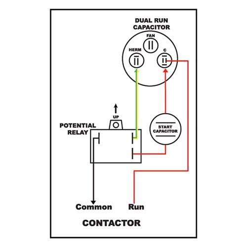
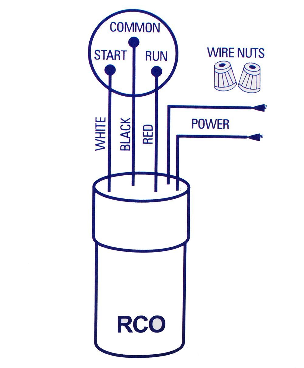
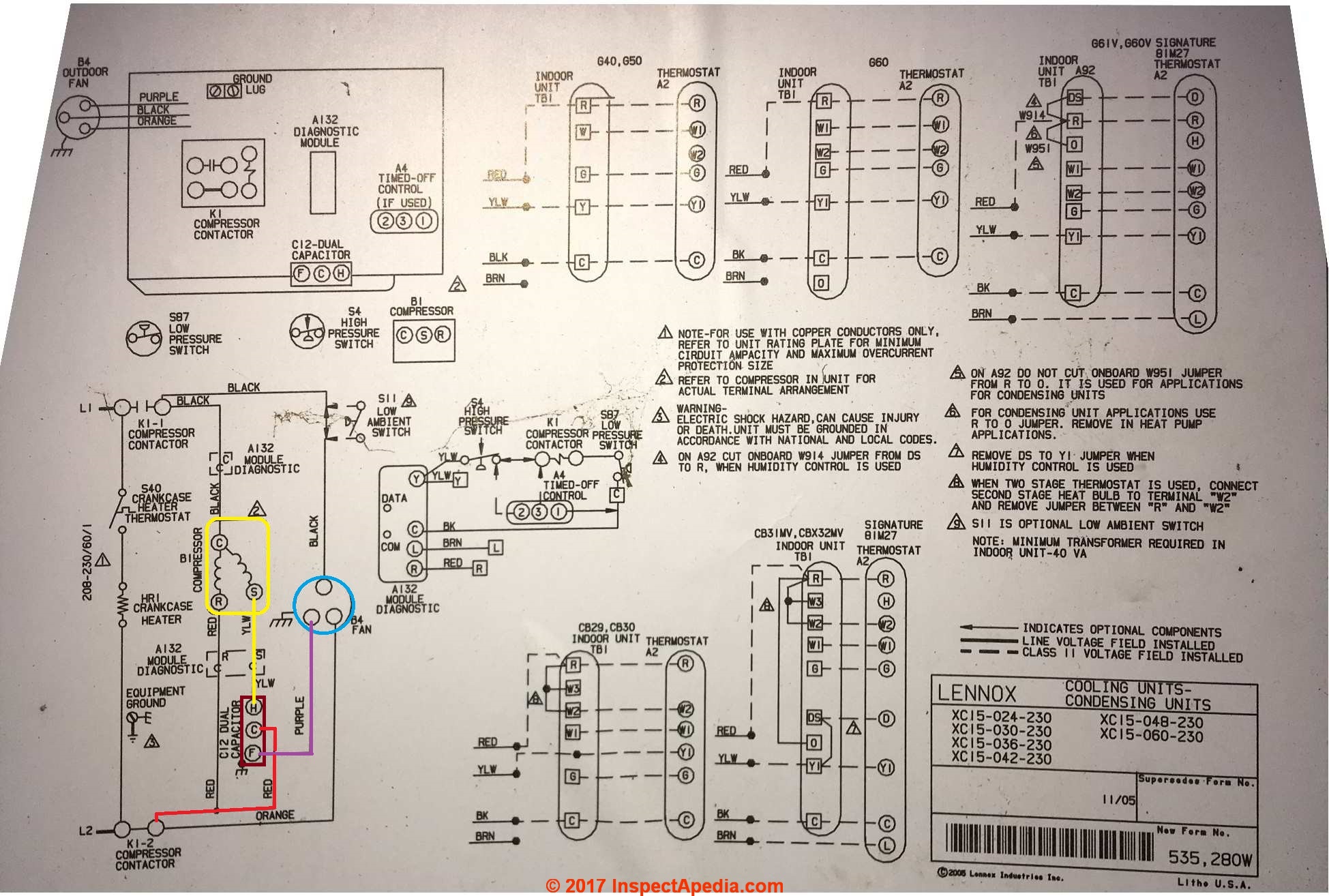
The diagram identifies the capacitor and relays wire color and the wires function. Figure one 1 shows the wiring diagram for the oem style 3 wire hard start.

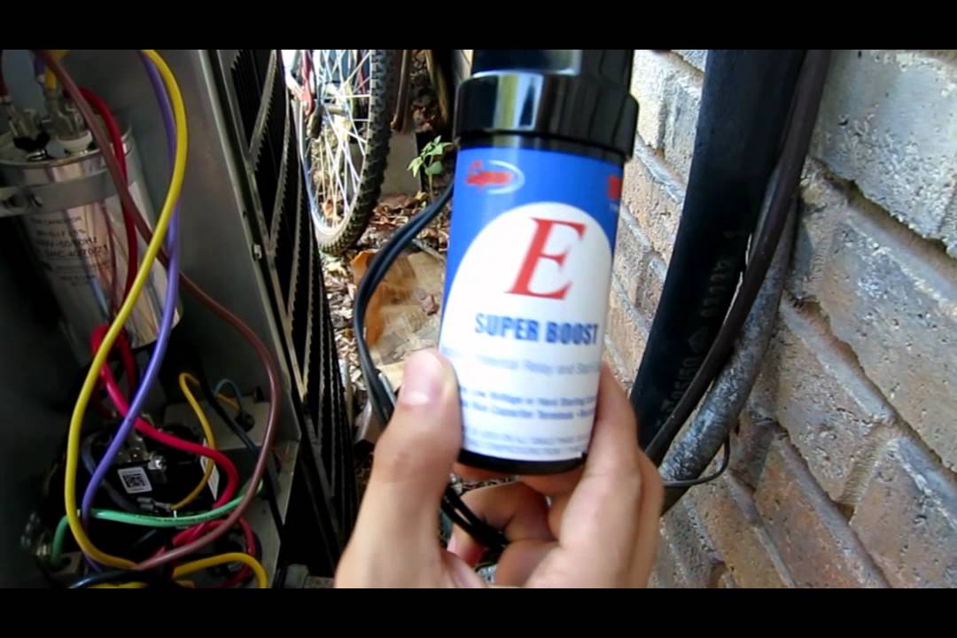
Hvac Repair Installing A Compressor Hard Start Kit
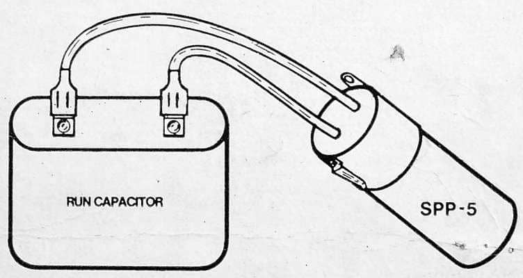
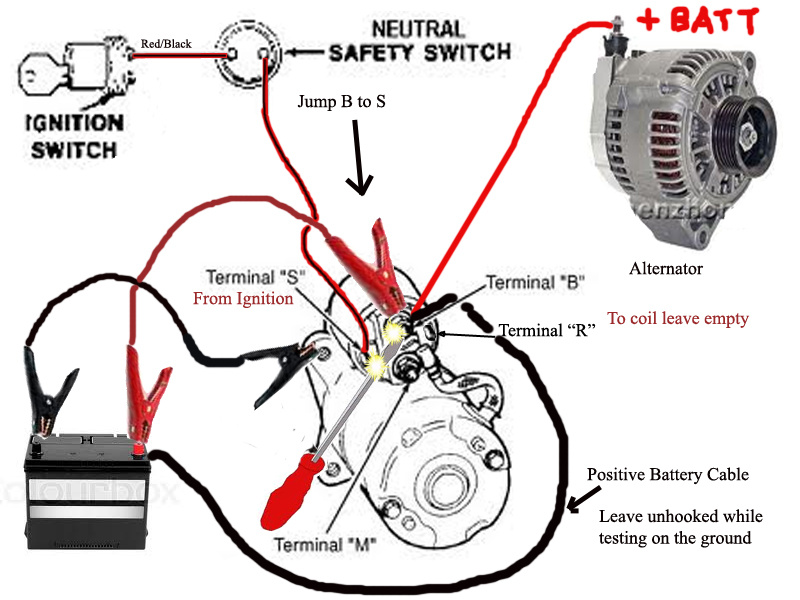
Hard start wiring diagram. 1car starter wiring diagram non relay control type. Quoting from part no. Spp 5 a relay and hard start capacitor sold by that company. The relay takes the start capacitor out of the circuit after startup. Simple relay and hard start capacitor wiring instructions example 1. Kit pn start capacitor nasa003sc hc95de088 88108 µf 330 vac.
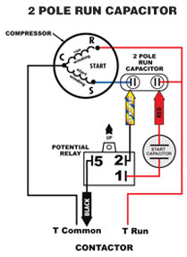
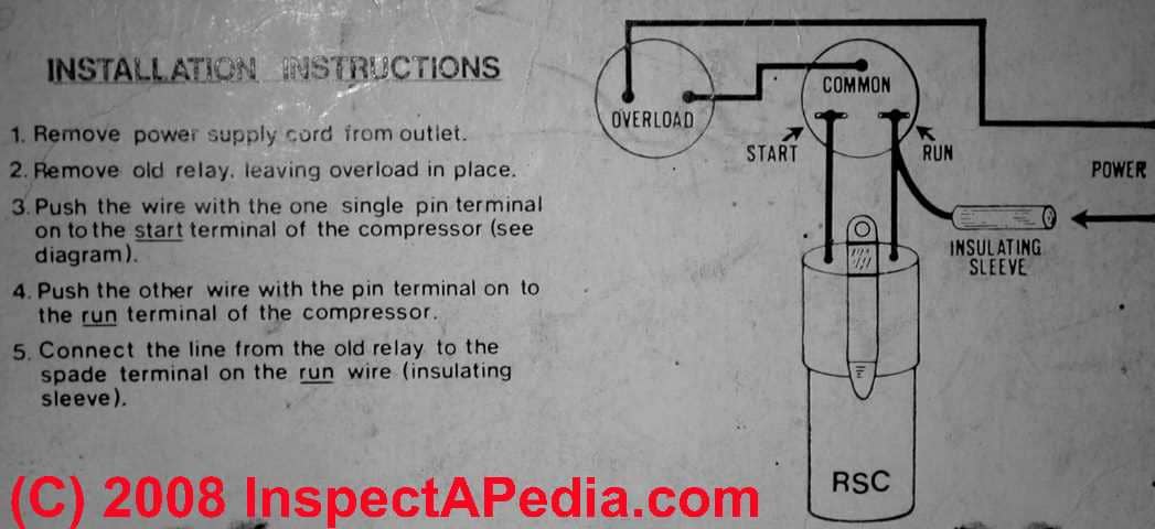
Relay and hard start capacitors such as the starter pow r pak sold by sealed unit parts co can be installed with no wiring changes to the original system whatsoever. Installation instructions start capacitor relay kit 2 482 01 5130 02 description and usage the start capacitor relay kit causes the start capacitor to give the compressor a hard boost at each startup. Step 3 push the wire terminal on the start capacitor relays common wire usually the black wire to the common terminal on the load side of the. Inspect the start capacitors wiring diagram. This is the procedure and information for adding or replacing a hard start on an existing systemthe specific unit in this example is a carrier brand ground level split straight cool system. The starter relay is another switch that is used to control the starting circuit.
In the start control circuit the relay is connected in series with the battery to shorten the transmission of the large current cable length. Figure 1 3 wire connection the potential relay opens at manufacturers specified voltage across the start winding of the motor effectively removing the start capacitor from the circuit. A third wire is necessary to connect to the common wire. This procedure applies to almost every air conditioning and heat pump system on the market. Often a stamp on the side of the relay shows the wiring diagram.
Gallery of Hard Start Wiring Diagram