In this video you can see how to find the relay in the fuse for engine. How to fix a glow plug problem in a 19 tdi engine volkswagen passat in this case but mostly these problems is in other cars.

Starting System Circuit Toyota Land Cruiser Engine Repair
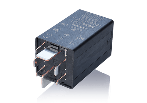
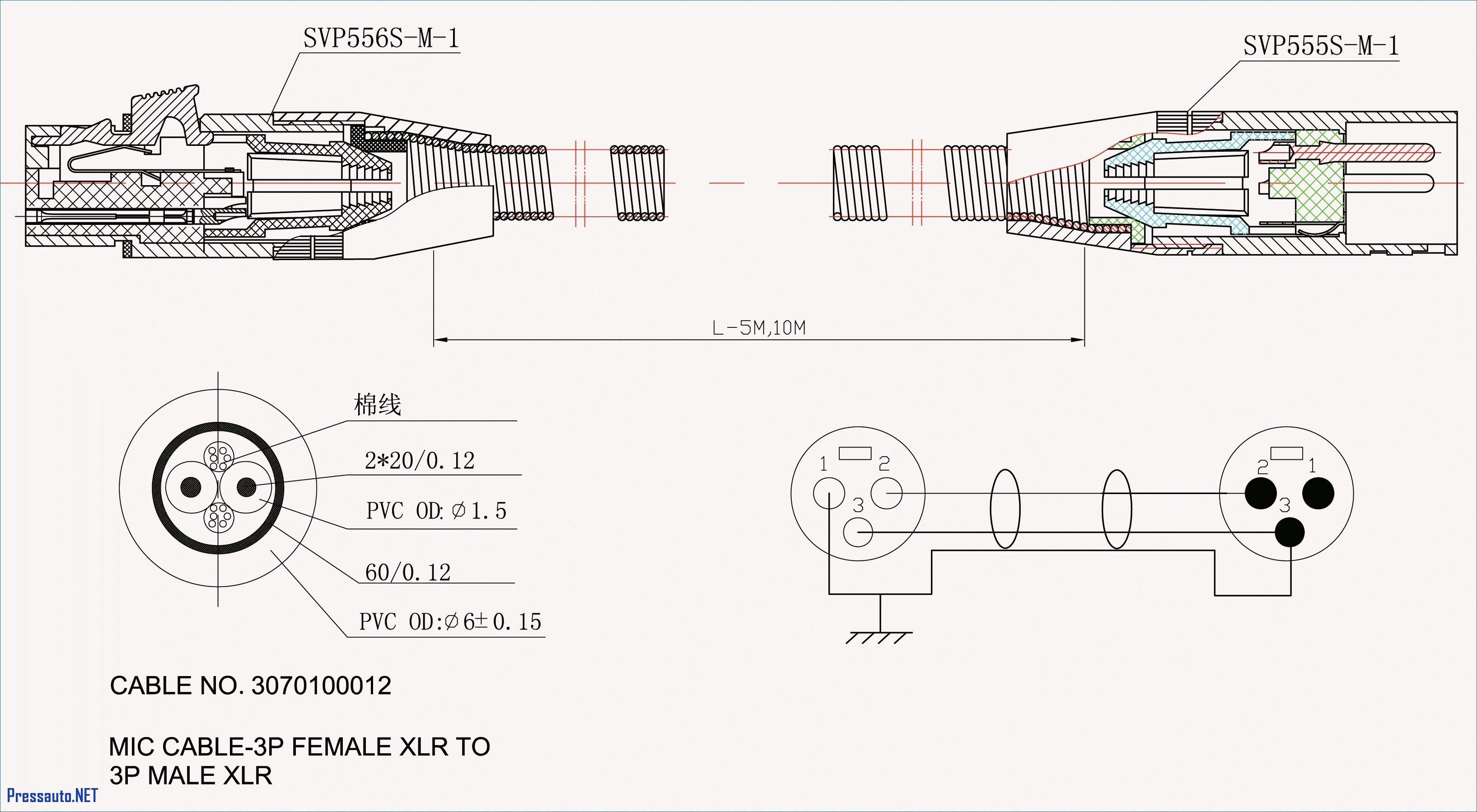
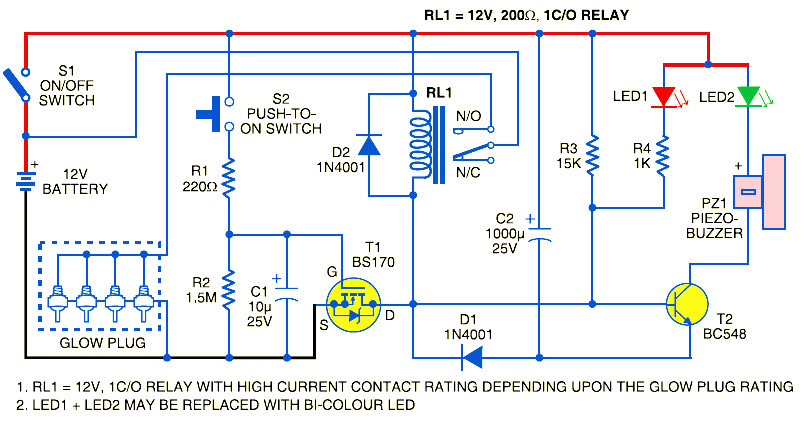
Glow plug timer wiring diagram. I have an fsm dated 1977 with a wiring diagram labelled land cruiser bj4043 electrical wiring diagram except usa. If the images produced less suitable way you can look for it using the search box. No start ford 7 3l idi diesel glow plug relay ing repair. The glow plug relay or timer is a fairly simple circuit built around a quad low power voltage comparator lm2901 a high current relay a couple of transistors diodes resistors and capacitors. Turn key switch to ignition on. A wiring diagram is a simplified standard photographic depiction of an electrical circuit.
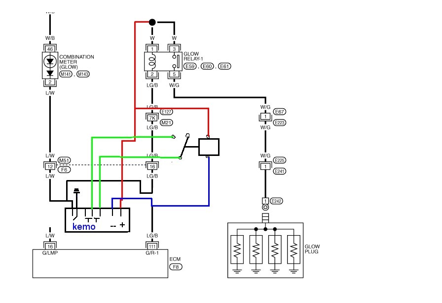
The circuitry is designed to provide a couple of variable delays after application of power via the glow and start positions on the ignition switch. 1983 ford f250 6 9 diesel glow plug relay manual bypass. Here ya go corvairwild i found it. Orange wire to glow indicator light and switched to negative in glow timer. One thing to watch is that sometimes the white wire and the yellow wire can be easy to mistake since the white one might look a little yellow. 73 powerstroke glow plug relay wiring diagram sample 1997 7 3 glow plug relay wiring diagram fresh whats needed to make a.
It reveals the parts of the circuit as simplified shapes and also the power and signal links between the devices. Posted by t nugraha at 1115 pm. Collection of 73 powerstroke glow plug relay wiring diagram. Red wire to key switch ignition on position. Glow plugs are powered up and the indicator light is on. Blue wire to ignition switch start position.
White wire to glow plug pre heat relay. Yellow wire to glow plug after glow relay. See if you can ground out that terminal with the blue wire and your relay should go click click. 6 9 diesel glow plug wiring diagram awesome glow plug relay with. I think that the one that is supposed to be white will have continuity to the ground wire until the controller turns off the gps. Canada which shows 5 terminals on the glow plug relay b from the 24v battery st from the sart position of the ignition switch g from the glow position of the ignition switch s which is connected to the b contacter in the relay another labelled g which is contacted.
Gallery of Glow Plug Timer Wiring Diagram