Thank you for the board and fritzing file. Game boy zero guide part 4 mounting and wiring wermy.
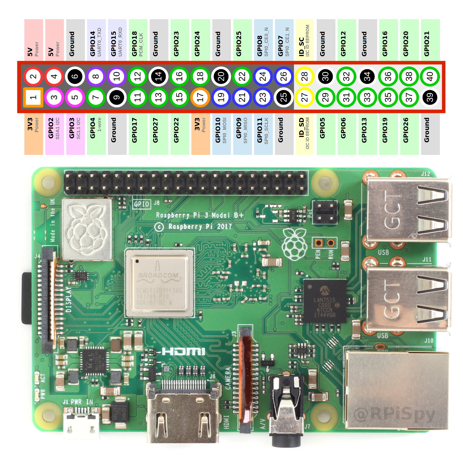
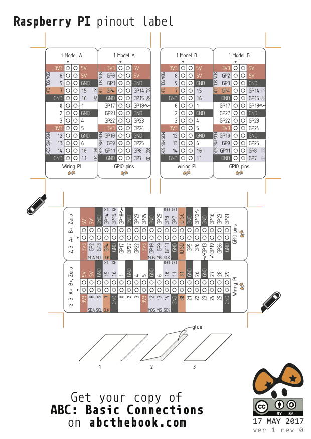
Simple Guide To The Raspberry Pi Gpio Header Raspberry Pi Spy
Gameboy zero wiring diagram. It provides a guide to the known hardware information pertaining to the hand held game boy console. Check out the cheapest gbz only 37 total. Gameboy link port output format heres assembly code a timing diagram and a circuit for controlling external projects with a gameboy. A dmg cartridge wont fit with rl buttons. A subreddit dedicated to discussion of the nintendo game boy. Find all of your bad boy lawn mowers parts here.
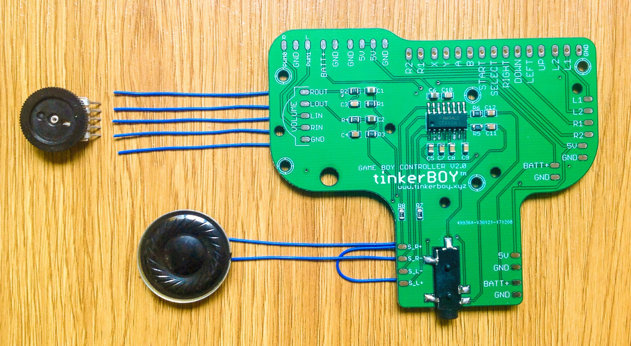
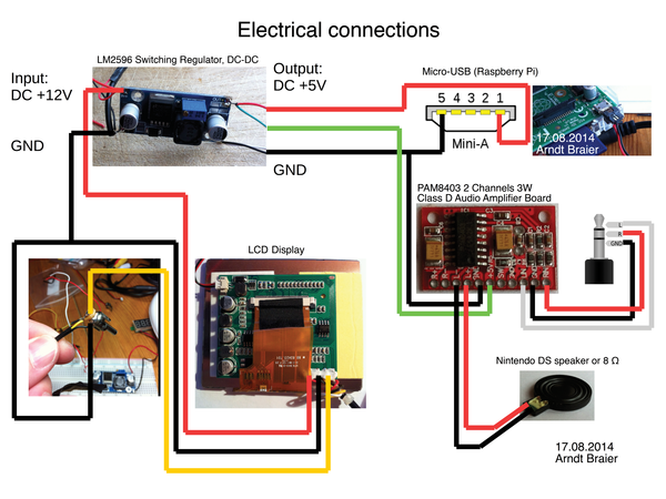
At helders all in one gameboy zero pcb. Desoldering the headphone jack and wiring it up to the amplifier and speaker. All in one board wiring diagrams using. Thank you for the wiring diagram and instructions. Home game boy zero wiring diagram for tinkerboy controller v30. We are your bad boy zero turn mower parts source.
Introduction this document was written to aid in the development of hardware and software for use with the nintendo game boy. Based on at cannikins wiring diagram. Also included is an 8 bit parallel port example project using an harristm 82c55a in an add in gb. Ive just completed my first gameboy zero build using a rpi zero. Audio diagrams from at helder and at fleder. Posted on august 9 2018 may 9 2019 by tinkerboy 42 comments wiring diagram for tinkerboy controller v30.
The game boy project 0. Based on at cannikins wiring diagram. If you dont know the bad boy zero turn part number you need check out our parts lookup function to search part diagrams for your machine. Thank you for the wiring diagram. 1 day build of a game boy zero with a 27 pcb with audio build in. Discussion of all game boy models handheld swaps mods games and.
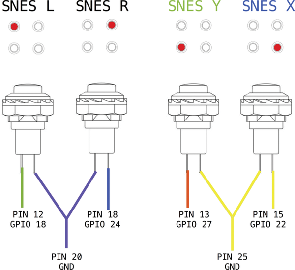
Gameboy link port io heres a circuit for controlling 16 digital outputs reading 16 digital inputs with a gameboy. At helders all in one gameboy zero pcb. Wiring diagrams v30 with at cambles graceful shutdowns. Gameboy advance gba cartridge. For the pi 3 just wire the data pins to the corresponding pins on the v3 controller board. You can add as many digital outputs as you want to this port.
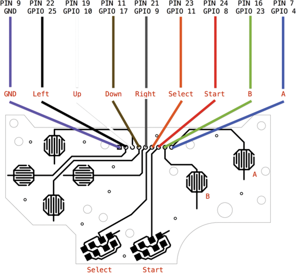
I soldered all of the wires to the pi following the wiring diagram above and also properly burned the above retropi 43 image with gpio button support and when i turned it on to test it everything worked as expected except my down button and my x button.
Gallery of Gameboy Zero Wiring Diagram