Galls 100w remote siren now includes mounting brackets replaceable jumpers for option selection and automatic short circuit protection against speaker shorts. My galls street thunder siren.
Galls St160 Siren Wiring Diagram Galls Street Thunder
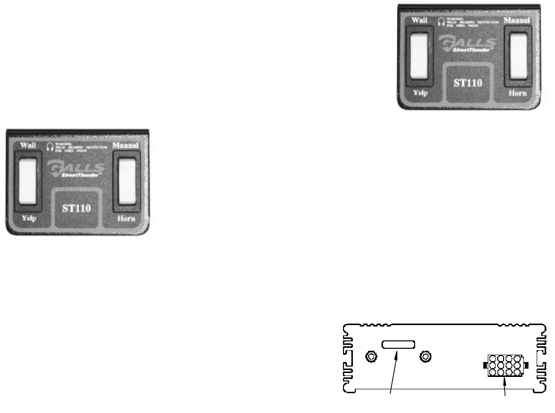
Galls st110 wiring diagram. Wiring diagram 5 operation 7 9 general 7 power 7 selector switch 8 manualhorn rocker switch 8 volume controls 9 microphone 9 auxiliary input 9 park kill 10 service 10 12. Upgraded to meet even more of your needs. Galls provides a preaddressed label for ou to affix to the y package. Hey everyone i got a galls st110. See the wiring diagram on page 6 for wiring details. Please try again later.
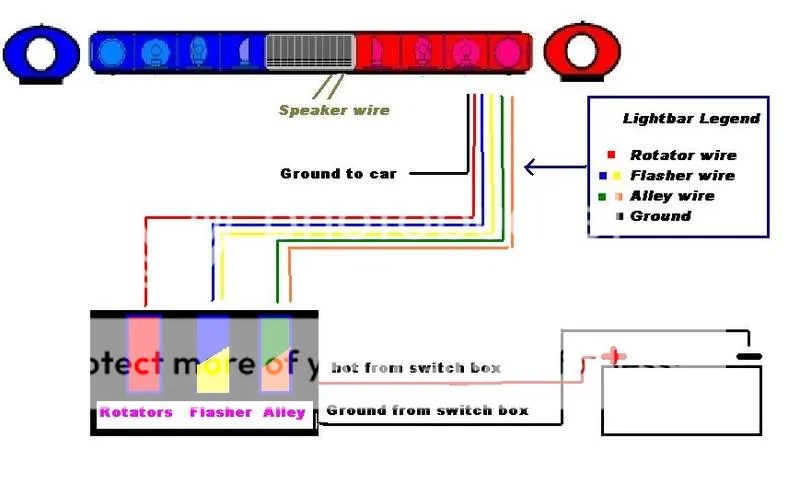
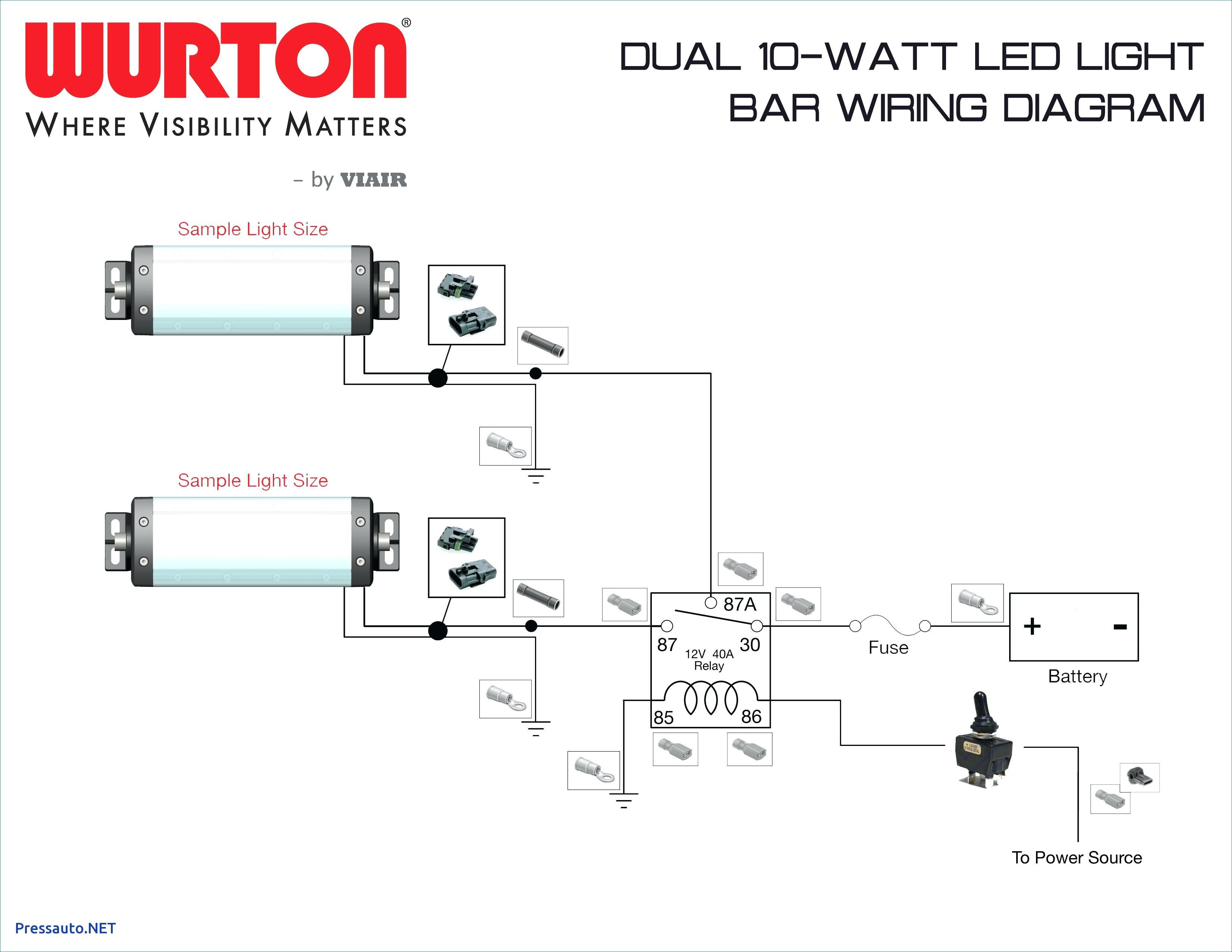
A wiring diagram on page 8 shows detail of how to wire the siren to the vehicle. Galls makes no warranty of any kind with regard to this manual including but not limited to the implied. Source is directly at the vehicle battery. Galls 100w remote siren. 100 watt output 2 outputs with 4 functionality opti. So im going to buy some new connectors to put in the harness but what pins.
This feature is not available right now. Galls street thunder 100w remote siren w2 light control is a handheld remote with an unbelievable price. On the wire harness the wires for those 2 functions are gone out of the harness so are the connectors. This feature de activates the vehicle horn while pushbutton switch s5 is activated. Do not mount in air bag deployment area. I received it today and the old owner had not used manual or horn functions.
Optional hrt wiring diagram electrical connections contd horn ring transfer hrt wiring diagram use this wiring diagram if you are connecting the orange wire to utilize the horn ring transfer feature. Separate switch panel for mounting the amp remotely under the seat or in the trunk. Box 54308 lexington ky 40505 tel. Devices should be mounted only in locations listed in sae standard j1849. Galls makes no warranty of any kind with regard to this manual including but not limited to the implied warranties of merchantability and fitness for a. Wiring 5 wiring diagram 6 operation 7 8 manual 7 workmanship under normal use and service for a period of seven 7 years from horn 7 auxiliary input 8 service 9 11 troubleshooting 9.
If you dont have your packing slip place the item in. St110 siren amplifier wremote switch panel installation and operating instructions 1340 russell cave road po. The unit is internally fused. St110 siren amplifier. Wire size and termination the wiring diagrams on pages 8 and 10 show the minimum wire size used for each connection along with recommended lead color.
Gallery of Galls St110 Wiring Diagram