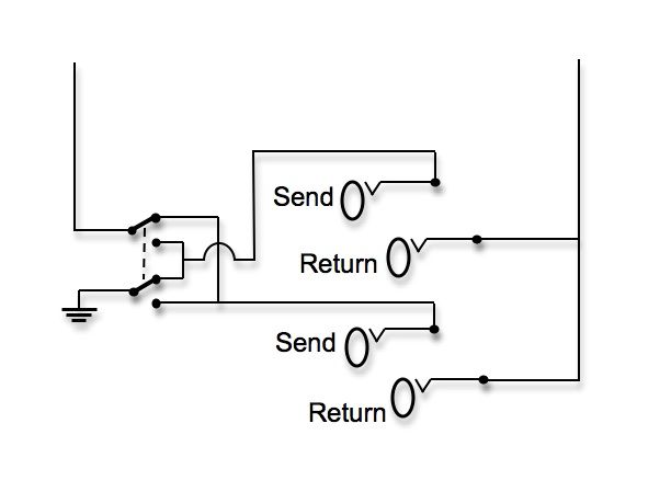
Please refer to the following diagram it is absolutely necessary to wire the ss terminal. Hands on how to wire a trigger switch for fix mode hazard auto off if signal light and hazard on duration.
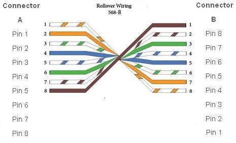
Comptia Network Different Types Of Cabling Standards
Fx mode wiring diagram. 3ø wiring diagrams 1ø wiring diagrams diagram er9 m 3 1 5 9 3 7 11 low speed high speed u1 v1 w1 w2 u2 v2 tk tk thermal overloads two speed stardelta motor switch m 3 0 10v 20v 415v ac 4 20ma outp uts diagram ic2 m 1 240v ac 0 10v outp ut diagram ic3 m 1 0 10v 4 20ma 240v ac outp uts these diagrams are current at the time of publication. Rs 485 communication and power wiring diagram15 figure 4. Simple fx mode diagram presentation. This thread wont get as full as there are only so many boards. Fx3u input wiring caution this notice is wholly designed to explain the fx3u dc input type sinksource input wiring variation to users of the exclusive sink input type model. Led blink sequence 17 figure 5.
Type model no max load supports notes diagram. Unsubscribe from dhiko mech. If in doubt at any stage of the installation of the fx 10gmfxe 20gm unit. This manual contains text diagrams and explanations which will guide the reader in the correect installation and operation of the fx 10gmfxe 20gm unit. If you do use the output the led may be ran at too high or too low. Subscribe subscribed unsubscribe 189k.
2005 mr luke should be ran off of 45 6v. 420 ma output wiring diagram 13 figure 3. Fx luminaire is an industry leading manufacturer of landscape and architectural lighting products with a focus on the advancement of led landscape lighting technology and digital lighting control with zoning dimming and color adjustment capabilities. Fx3u external input wiring can be either sink method or source method. Page 31 shld at the sensor not touching the metal enclosure and properly grounded at the readout unit. Fxs shovel kickelectric no turn signals ignition switch hilo horn horn switch tach speed hi beam oil light neutral light oil switch neutral switch electronic distributor alternator headlight run switch starter switch voltage regulator starter motor starter solenoid 30 a breaker battery bus starter relay taillight 30 long bolt top hot cable cable short bolt bottom.
Wiring can interfere with controller communication. Wiring diagram for hazard fx mode dhiko mech. Mrhasbro fx wiring diagrams this will be run like the cheapy hasbro thread. The ec fx nh3 is. Place the ec fx detector in cal. Credit goes to tim.
Pm me with submissions. You do not need to use the led output of the board. Before attempting to install or use the fx 10gmfxe 20gm unit this manual should be read and understood. Kamotobiker recommended for you. Fx pcg16 general purpose programmable. Do not support passthrough in the commissioning mode do not support remote downloading or commissioning using bacnet routing part no.
Gallery of Fx Mode Wiring Diagram