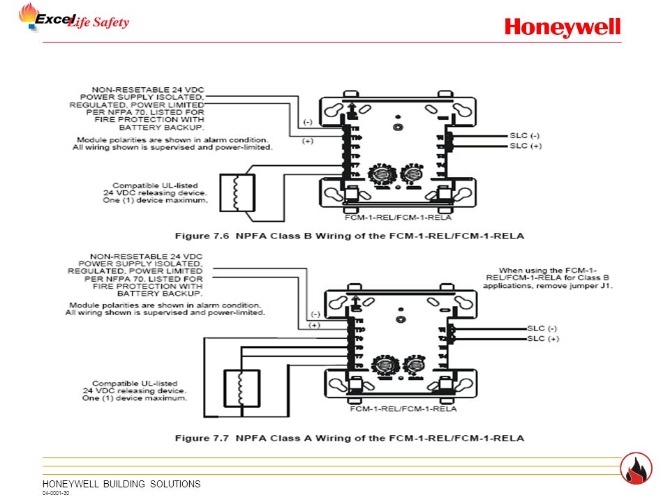
Relay module wiring diagram. Install module wiring in accordance with the job drawings and appropriate wiring diagrams.
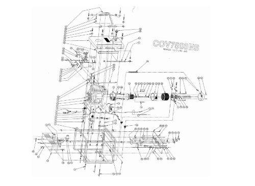
Cov7500 Es Parts List Amp Wiring Diagram Pre Winco Generators
Frm 1 wiring diagram. Maximum slc current draw. A wiring diagram is a simplified conventional pictorial representation of an electric circuit. Removing general description rotary switch stop. Module mounting with barrier. Typical notification appliance circuit configuration nfpa style y. Any number of ul listed contact closure devices may be used.
Removing rotary switch stop. Surface mounted electrical boxes smb500 are available from notifier. 4675 h x 4275 w x 14 d mounts to a 4 square by 218 deep box specifications for frm 1. Maximum slc current draw. 15 to 32 vdc maximum current draw. Class b supervised wiring to the monitored device.
Page 5 wiring diagrams this page. The fcm 1a is configured for a single class b style y or class a style z notification appliance circuit. Typical fault tolerant notification appliance circuit configuration nfpa style z. The power limited wiring must be placed into the isolated quadrant of the module barrier figure 2b. Set the address on the module per job drawings. 32f to 120f 0c to 49c dimensions.
When using control modules in. The frm 1 mounts directly to 4 square electrical boxes see fig ure 2a. Module polarities are shown in alarm. Class a supervised wiring to the monitored device. Install contact closure devices per manufacturers installation instructions. Variety of notifier fcm 1 wiring diagram.
All wiring shown is supervised and power limited. Transmits the status of one zone of 2 wire detectors to the fire alarm control panel. Fzm 1 zone interface monitor module. Page 1 figure 1. Connect modules to listed compatible notifier control panels only. 15 to 32 vdc.
The frm 1 relay control module is intended for use in intelligent two wire systems where the individual address of each module is selected using the built in rotary switches. Fmm 1 connect modules to listed compatible notifier control panels only. 65 ma led on. 65 ma led on temperature range. 15 to 32 vdc. Operation each fcm 1a or frm 1a uses one of 159 possible module addresses on a slc loop 99 on clip loops.
It reveals the parts of the circuit as streamlined forms and the power as well as signal links in between the tools. All wiring must conform to applicable local codes ordi nances and regulations. Secure module to electrical box supplied by installer see figure 2a. A78 2611 11 a78 2610 08 specifications normal operating voltage. All wiring shown is supervised and power limited. It allows a compatible control panel to switch discrete contacts by code command.
The frm 1a provides two form c dry contacts that switch together. Install module wiring in accordance with the job drawings and appropri ate wiring diagrams. Fmm 101 mini monitor module. The box must have a minimum depth of 21 8. Smaller size fits inside devices or junction boxes.
Gallery of Frm 1 Wiring Diagram