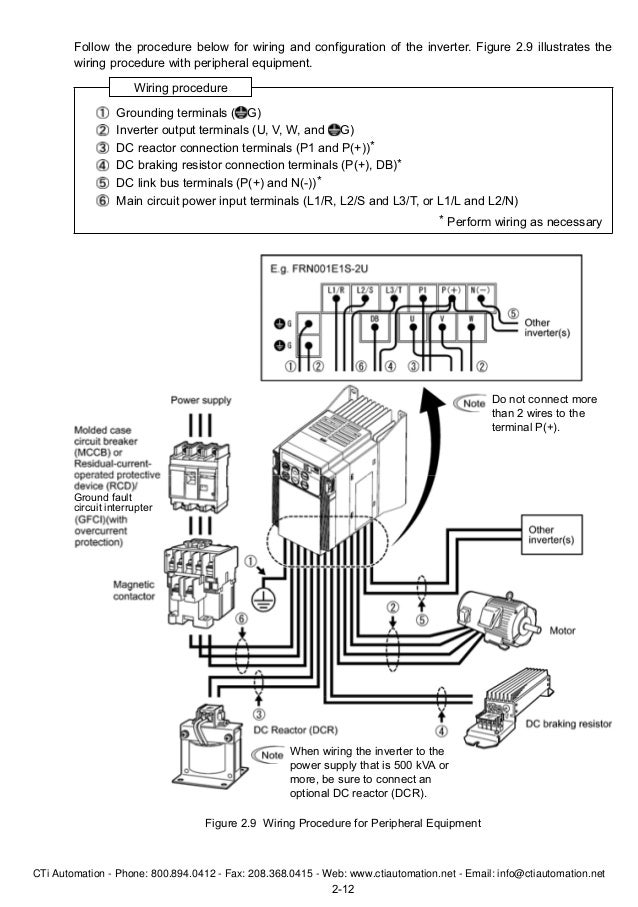
Wiring 8 31 removing the terminal cover and the main circuit terminal block cover 8 32 wiring for main circuit terminals and grounding terminals 10 33 wiring for control circuit terminals 10 34 connection diagram 16 35 setting up the slide switches 17 4. Wiring for main circuit terminals and grounding terminals.

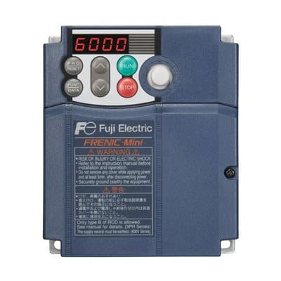
Fuji Frenic Mini C1 Drives General Specifications Manualzz
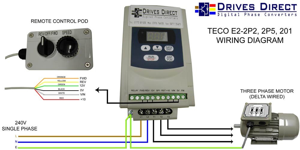
Frenic mini wiring diagram. Quick start commission 21. Wiring length between inverter and motor. Connection diagram in operation by external signal inputs. Fuji frenic mini drive connection diagram 3 wire mode potentiometer start stop wiring hindi duration. The frenic mini series employs such noise reducing schemes as a structure that cuts off the transmission path for the fet of the control power supply. Operation using the keypad 19 5.
Fuji electric motor wiring diagram wiring diagram database electrical starting guide frenic multi fuji electric instruction manual fuji electric corp of america fuji frenic mini drive connection diagram 3 wire mode potentiometer start stop wiring hindi motors applied products fuji electric global single phase motor wiring diagrams north. Moreover in former models a noise reducing emc filter was an optional external attachment. Fuji electric frenic mini pdf user manuals. Fuji electrics new frenic mini c2 series provides excellent performance for both single phase and three phase applications and is available in multiple configurations to support 18 hp up to 20 hp ac drives variable frequency drives vfd v hz vector drives. But an internal emc filter has been developed for the frenic mini series in compliance with the european. With an expanded range of rated voltages the new frenic mini c2 strikes.
Frenic mini c2 control wiring note 1. Compliance with emc standards. Frenic mini may not be used for a life support system or other purposes directly related to the human safety. Do not use it for single phase motors or for other purposes. And follow the instructions contained in the frenic mini instruction manual chapter 7 section 74 insulation test control circuit wiring length when using remote control limit the wiring length between the inverter and operator box to 656 ft 20 m or less and use twisted pair or shielded cable. View online or download fuji electric frenic mini user manual instruction manual.
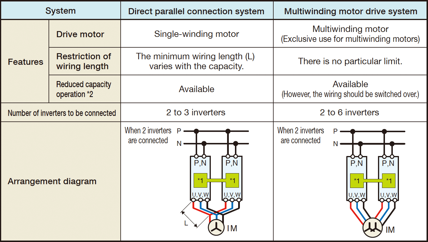
For single phase 100v input series dcr shall be connected to the point that is shown below. Fire or an accident could occur. Frenic mini is designed to drive a three phase induction motor and three phase per manent magnet synchronous motor pmsm. Genus controls 9735 views. When connecting a dc reactor dcr option remove the jumper bar from across the terminals p1 and p. 1112 considerations when using frenic mini in systems to be certified by ul and cul if you want to use the frenic mini series of inverters as a part of ul standards or csa standards cul certified certified product refer to the related guidelines described on page ix.
Gallery of Frenic Mini Wiring Diagram