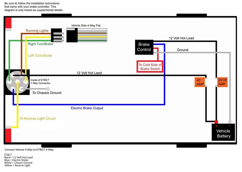
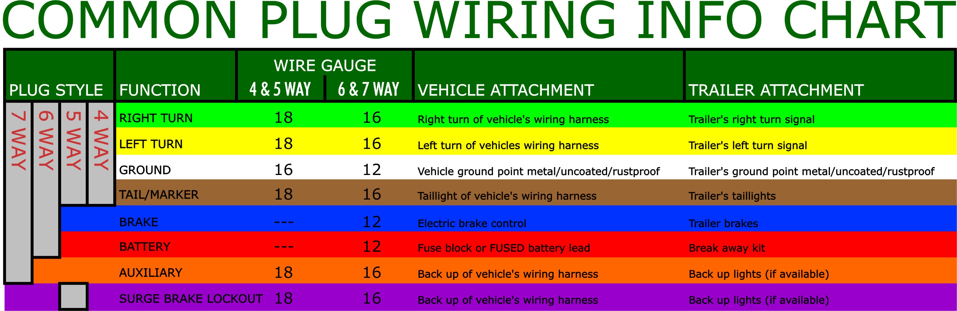
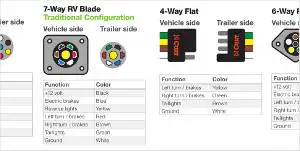
1 4 wire the first 4 pins white brown yellow green just like the 4 pin connector above. White pin for the ground.

Battery Charging Wiring Harness Gas Trailer
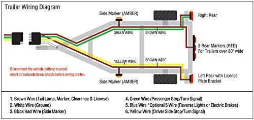
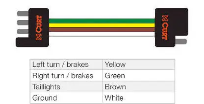
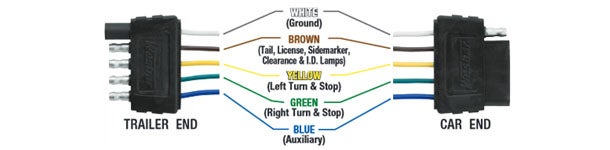
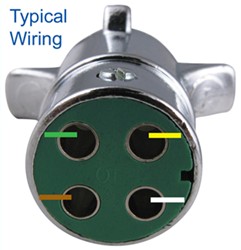
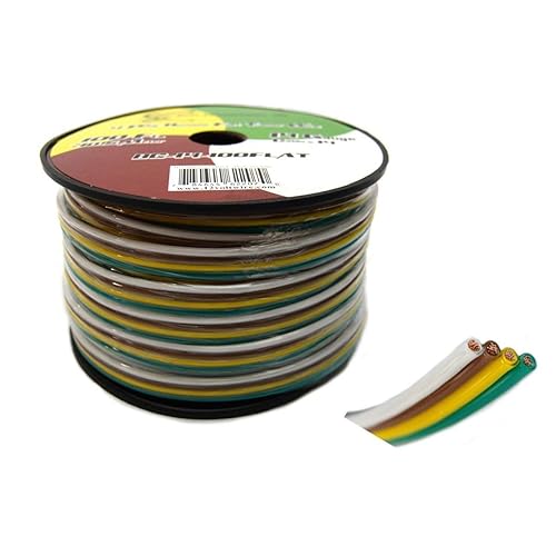
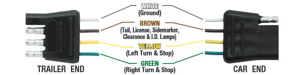
Four prong trailer wiring diagram. You must check the trailer manual to see if the wiring is correct but normally the white wire is called the ground wire while the brown wire is used for tail lights. This 4 prong trailer wiring diagram model is more suitable for sophisticated trailers and rvs. It can transfer power better hence the connector is suggested for higher level electric in the auto. 34 inch by 1 inch 6 way rectangle connectors right turn signal green left turn signal yellow taillight brown ground white. As the name implies they use four wires to carry out the vital lighting functions. It reveals the elements of the circuit as simplified shapes as well as the power and also signal links in between the gadgets.
Can also be used as custom wiring on trailers with 3 lightwire systems. 4 way trailer connectors are. Yellow and green are for left and right turns and braking. Blue electric brakes or hydraulic reverse disable see blue wire notes below in the trailer wiring diagram and connector application chart below use the first 5 pins and ignore the rest. A wiring diagram is a streamlined traditional photographic representation of an electrical circuit. 4 way trailer connectors are typically used on small trailers such as boat snowmobile utility and other trailers that that do not use brakes.
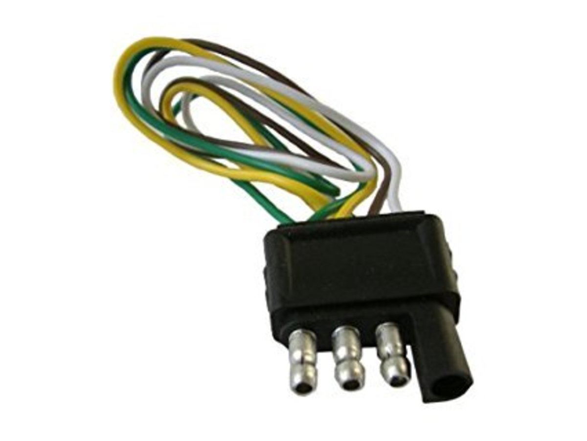
Here is the diagram for 7 pin connector. Use on a small motorcycle trailer snowmobile trailer or utility trailer. Collection of 4 prong trailer wiring diagram. Installing the 4 pin trailer wires. The four wires control the turn signals brake lights and taillights or running lights. The red and blue wire can be used for brake control or auxiliary.
Start by cutting the white wire and attaching it to the trailer frame. Traditional trailer with brakes use a 5 pin connector. They also provide a wire for a ground connection.
Gallery of Four Prong Trailer Wiring Diagram