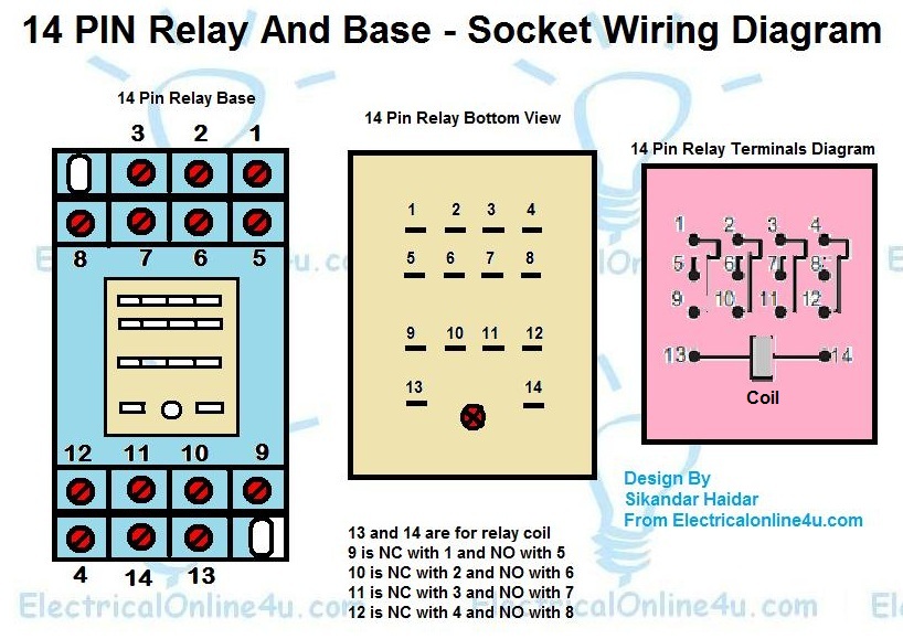
Otherwise the structure wont function as it ought to be. The wiring diagram is given below to help you wire it properly.
4 Pin Horn Relay Wiring Mah 124 A 1r Zhejiang Meishuo
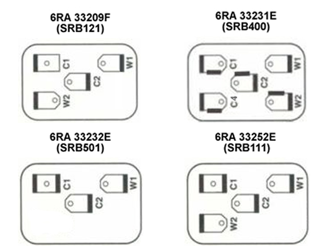
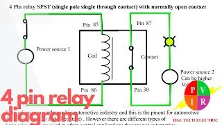
Four pin relay wiring diagram. There are 2 types of 4 pin relay available. Each component ought to be set and connected with different parts in particular way. 4x4 and off road forum inside relay 4 pin wiring diagram image size 640 x 480 px and to view image details please click the image. These layouts are shown on the two 5 pin relays below pin 87a not present on 4 pin relays. Wiring diagram for a 4 pin relay wiring diagram as well 3 pin flasher relay wiring as well 2 prong wiring diagram for a 4 pin relay wiring diagram is a simplified agreeable pictorial representation of an electrical circuit. You must check the trailer manual to see if the wiring is correct but normally the white wire is called the ground wire while the brown wire is used for tail lights.
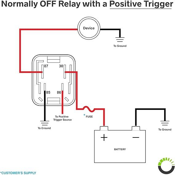
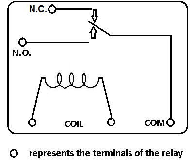
So if youd like to get these. This 4 pin relay comes with no labeling or wiring diagram. Relay diagrams pirate4x4. A normally open relay will switch power on for a circuit when the coil is activated. Start by cutting the white wire and attaching it to the trailer frame. Installing the 4 pin trailer wires.
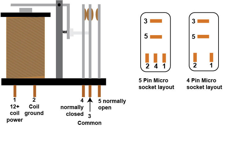
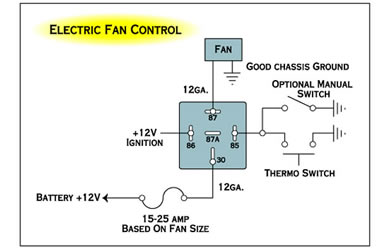
4 prong relay wiring diagram 4 pin flasher relay wiring diagram 4 pin relay wiring diagram 24v 4 pin relay wiring diagram fan every electrical structure consists of various unique pieces. 4 pin relay 4 pin relays use 2 pins 85 86 to control the coil and 2 pins 30 87 which switch power on a single circuit. 40 amp 4 pin relay wiring diagram on 40 images. I never write reviews but i figured this would be a good one since i researched hi and low to figure out how to wire. This wiring method is fully compatible with any 4 pin denso relay starting with the serial number 156700 or look like the sample denso relays below. Yellow and green are for left and right turns and braking.
Here is a picture gallery about relay 4 pin wiring diagram complete with the description of the image please find the image you need. It shows the components of the circuit as simplified shapes and the capacity and signal connections with the devices. Normally open or normally closed.
Gallery of Four Pin Relay Wiring Diagram