Basic construction of a fiber optic cable core. How does fiber optics work explain that stuff an easy to understand introduction to fiber optics fibre optics the different kinds of fiber optic cables and how light travels down them fiber optic designs and diagrams from versitron since 1958 fiber optic design drawings block diagrams for lan video data m applications if you need to quickly access examples of.
The Foa Reference For Fiber Optics Fiber Optic Lan
Fiber optic cable wiring diagram. Notes for wiring diagrams above. There is no difference in connectivity between 568b and 568a cables. See notes below 3. Core cladding coating strengthening fibers and cable jacket. Wiring diagram book a1 15 b1 b2 16 18 b3 a2 b1 b3 15 supply voltage 16 18 l m h 2 levels b2 l1 f u 1 460 v f u 2 l2 l3 gnd h1 h3 h2 h4 f u 3 x1a f u 4 f u 5 x2a r power on optional x1 x2115 v 230 v h1 h3 h2 h4 optional connection electrostatically shielded transformer f u 6 off on m l1 l2 1 2 stop ol m start 3 start start fiber optic. For patch cables 568 b wiring is by far the most common method.
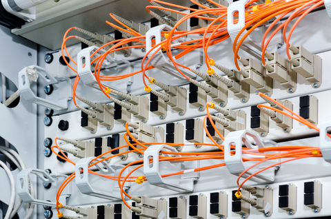
This is the physical medium that transports optical signals from an attached light source to a receiving device. For a straight through cable wire both ends identical. Either wiring should work fine on any system. The following picture shows the wiring diagram of the two standards. A fiber optic cable consists of five main components. There will be 64 strands of fiber optic cable emanating from a central point.
For this sample building to building fiber diagram i am presenting a fiber optic network that connects 16 buildings. However the t568b is considered better than t568a wiring standard. Fiber optic cable diagram. Fiber optic cable 29 fiber optic pigtail 3 fiber patch cable 20 mpo assemblies. When you are doing the straight through wiring the cable pinout on the two ends of the cat5e cable should be the same.
Gallery of Fiber Optic Cable Wiring Diagram