Controlled devices may be powered by 12 or 24v dc. Fibaro switch 2 allows to control connected devices either via the z wave network or via a switch connected directly to it and is equipped with active power and energy consumption metering functionality.

Rgb Fibaro Home Automation Smart Home Home
Fibaro rgbw wiring diagram. As with all other actors fibaro double relay switch allows to control connected devices either via the z wave network or via a switch connected directly to it. Notes for the diagrams. It is a visual rather than practical demo. The led light means the device is. P power power supply conductor red gnd ground ground conductor blue in1 input no. 1 in2 input no.
0 10v sensors wiring diagram. If the device fully assembled switch on the mains voltage or enable the power supply. Any questions just ask. Verify correctness of connection. Rgbw strip with 0 10 v potentiometer wiring diagram. 2 tp temppower power supply conductor of the ds18b20 temperature sensor brown 33v td tempdata signal conductor of the ds18b20 temperature sensor white ant antenna black out1 output no.
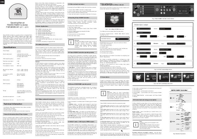
Rgbw strip wiring diagram. Fibaro rgbw controller 2 uses pwm output signal allowing it to control led rgb rgbw strips halogen lights and other resistive loads. Second connect voltage supply. Fibaro switch 2 is designed to be installed in standard wall switch boxes or anywhere else where it is necessary to control electric devices. Example connection of double smart module. Remember to keep the device away from water or protect holes for wires from water to avoid destroying the device.
Note the device must be powered by a dedicated stabilized power adapter. Hope you understand and enjoy the video. Connect with one of the diagrams below. Fibaro rgbw controller 2 is a universal z wave plus compatible rgbrgbw controller. Flood sensor diagrams and connection connecting the fibaro flood sensor in a manner inconsistent with manual may cause risk to health life or material damage. 1 assigned to input in1.
Fibaro double relay switch is designed to be installed in standard wall switch boxes or anywhere else where it is necessary to control two independent devices drawing up to 1500w each. Buy me a. First connect outputs rgbw rgbrgbwled diodes or halogen lights or inputs i1 i4. 4 fibaro rgbw controller must be powered by 12vdc or 24 vdc fibaro rgbw controllers operating modes. Turn the voltage on. Connect fibaro rgbw controller according to wiring diagram.
Arrange the antenna find tips below wiring diagrams. This short video describes the wiring of the fibaro z wave relays. It can also measure active power and energy consumed by the load. Halogen at 12v 144w combined actual voltage range eg. Tighten the terminal screws using ph1 screwdriver. Page 1 as shown in fig3 inputs set to work in analog mode require pviii and ix for operating modes detailed description.
Example connection of smart module diagram 2.
Gallery of Fibaro Rgbw Wiring Diagram