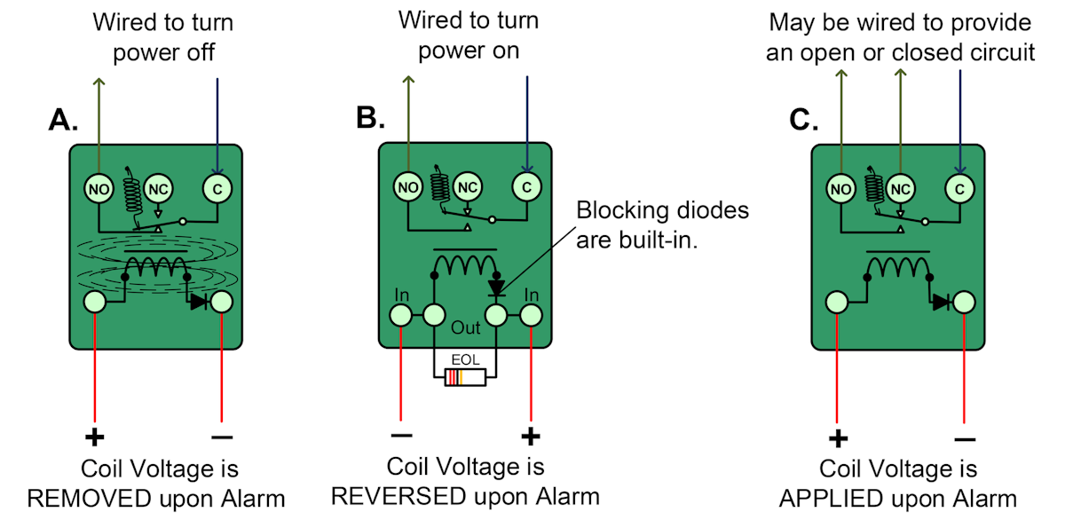
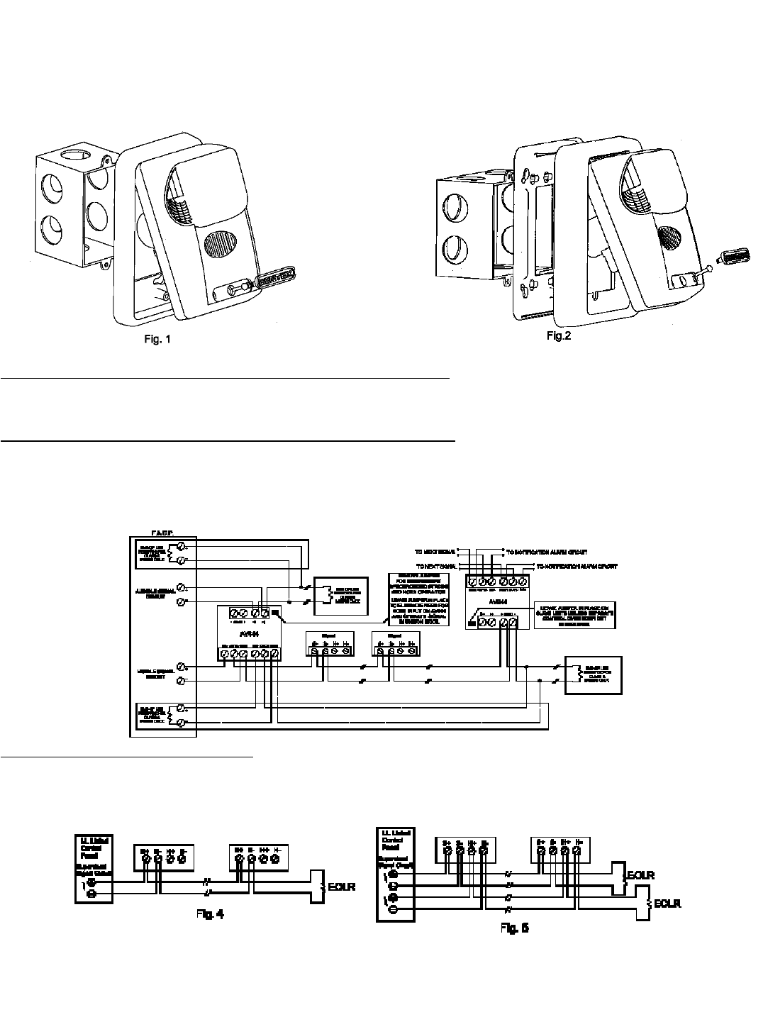
Connect the normally closed facp trigger input to the terminals marked input and wire a jumper to the terminals marked input and t on the terminal block labeled facp interface. Such a system however does not assure protection against prop erty damage or loss of life resulting from a fire.
Fire Alarm Class A Wiring Diagram Geboy 2012 Rmnddesign Nl
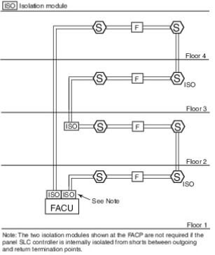
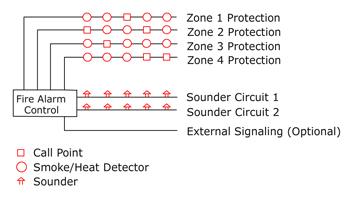
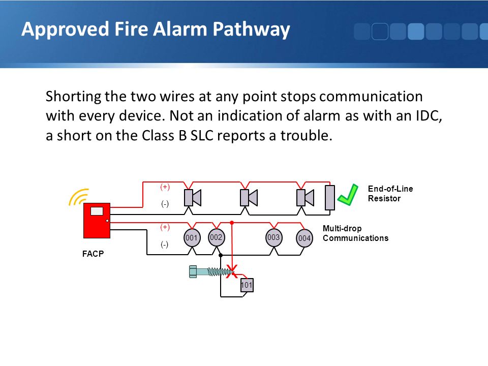
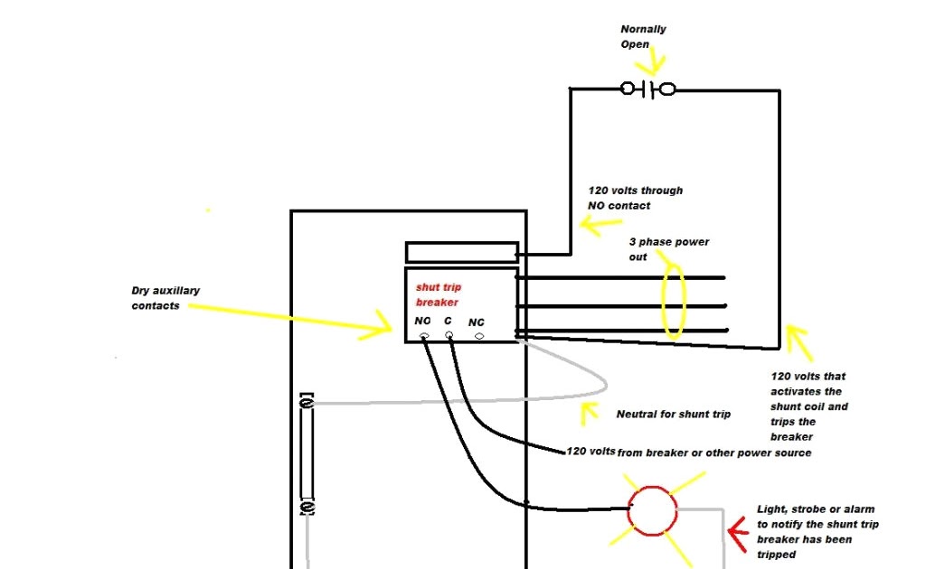
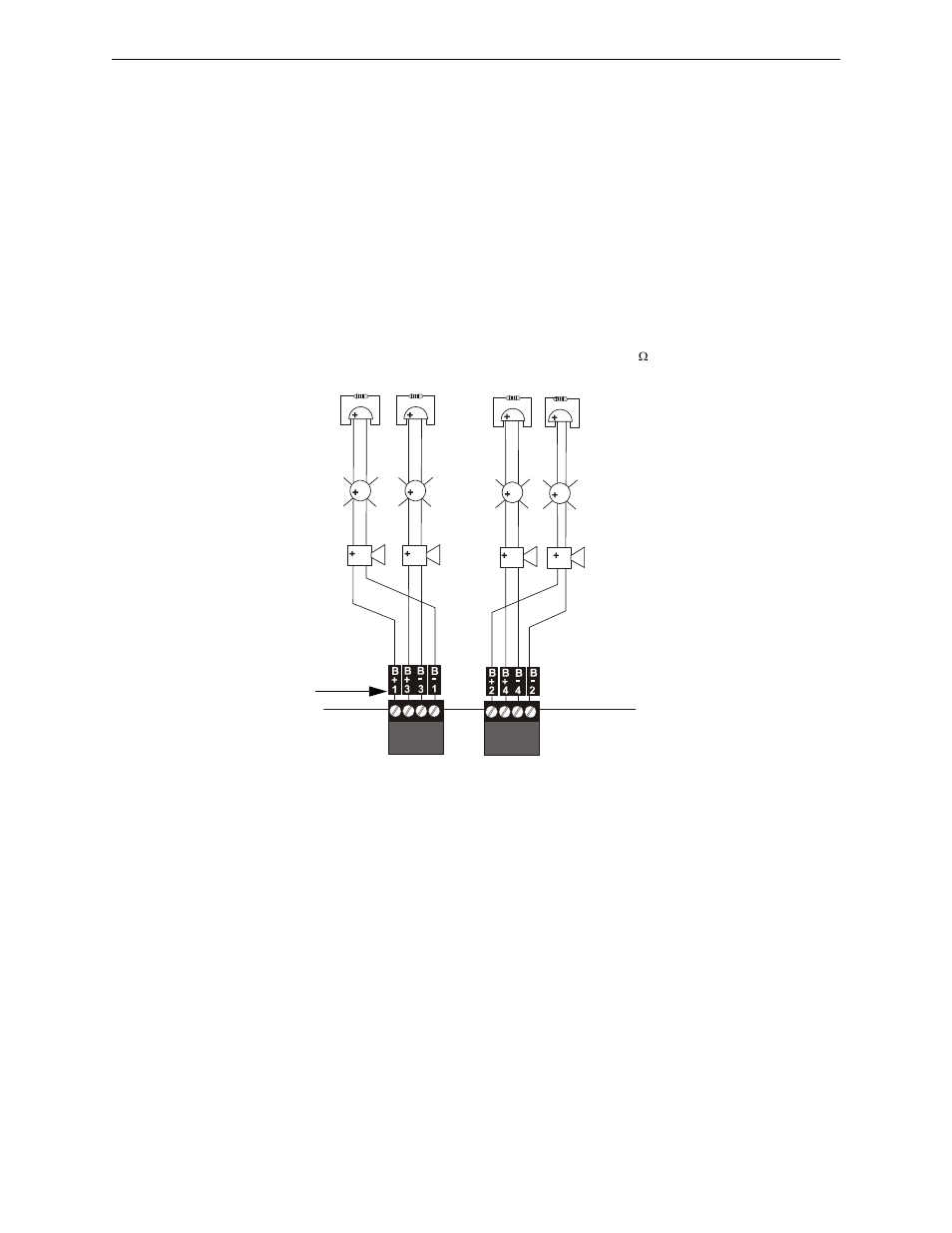
Facp wiring diagram. Smoke detectors heat detectors or manual call points can be fitted to each circuit. A of auxillary power connection for second ann bus synchronization of central stationremote station transmitter connection to facp dry contact. A maximum of 32 devices ie. Typical detector circuit wiring. Devices and a fire alarm control panel facp with remote notifica tion capabilitycan provide early warning of a developing fire. All devices must be polarised.
23 detector circuit wiring diagram the infinity comes with one two four six or eight detection circuits zones. Detector circuit wiring diagram. Also refer to rating information inside the facp. 2 nfs2 640e installation manual pn 52741k1 03062012 fire alarm system limitations while a fire alarm system may lower insurance rates it is not a substitute for fire insurance. The mains supply to the facp is fixed wiring using fire resisting 3 core cable between 1. C facp signal circuit trigger input.
And neg of the facps signal circuit to the terminals marked input. An automatic fire alarm systemtypically made up of smoke detectors heat detectors manual pull stations audible. Help me i need. An emergency communication system typically made up of an. Asking for wiring diagram.
Gallery of Facp Wiring Diagram