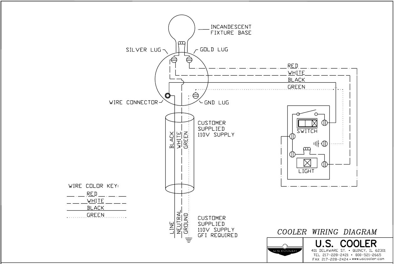
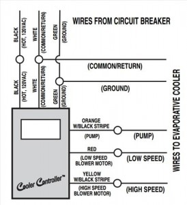
This diagram is a basic schematic and is not intended to represent all methods of installation because of various cord plug and pump configurations. Always follow the schematics that come with the switch that is bought this is only an example on the left side is the wiring coming from a breaker with black hot white common and green ground.

How To Wire Dual Electric Cooling Fans
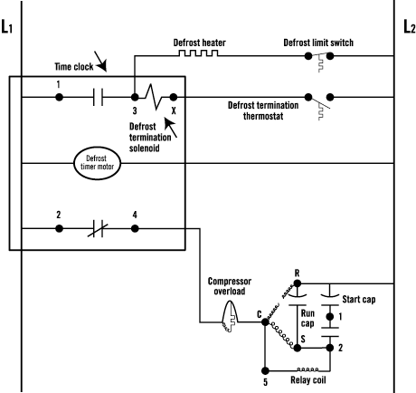
Evap cooler wiring diagram. The swamp cooler wiring. Refer to above diagram the green. The above is a basic wiring schematic for a swamp cooler switch. Determine first the best location for the switch. This diagram gives information of circuit. Httpsamznto2kx6lud click here for a complete write up on wiring a swamp cooler.
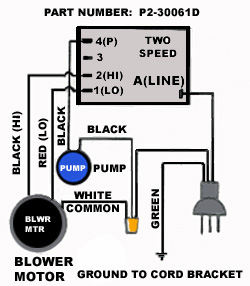
Amazon affiliate link to swamp cooler switch. Evaporative cooler switch wiring diagram wiring diagram swamp cooler switch wiring diagram. The diagram provides visual representation of the electrical arrangement. An evaporator cooler switch. Other wiring color codes to wire in the thermostat the above would be followed. See evaporative cooler installation instructions and motor and pump instructions for proper motor and pump wiring.
Be sure motor pump and cooler are properly grounded. The above is a basic wiring diagram of how to wire up a thermostat for swamp cooler. Here is how to wire up a 120 volt swamp cooler switch controller. For example l1 is labeled as power which is the black wire from the circuit breaker. All common wires white are tied together so the circuit is completed. On the other hand this diagram is a simplified variant of the structure.
Basic evaporator switch wiring schematic. This can be tricky as the route must communicate with unfinished space to the power source and also communicate with the attic. Once again if it is practical placing the switch on the outide of the flue chase can be a good option. It makes the process of assembling circuit easier.
Gallery of Evap Cooler Wiring Diagram