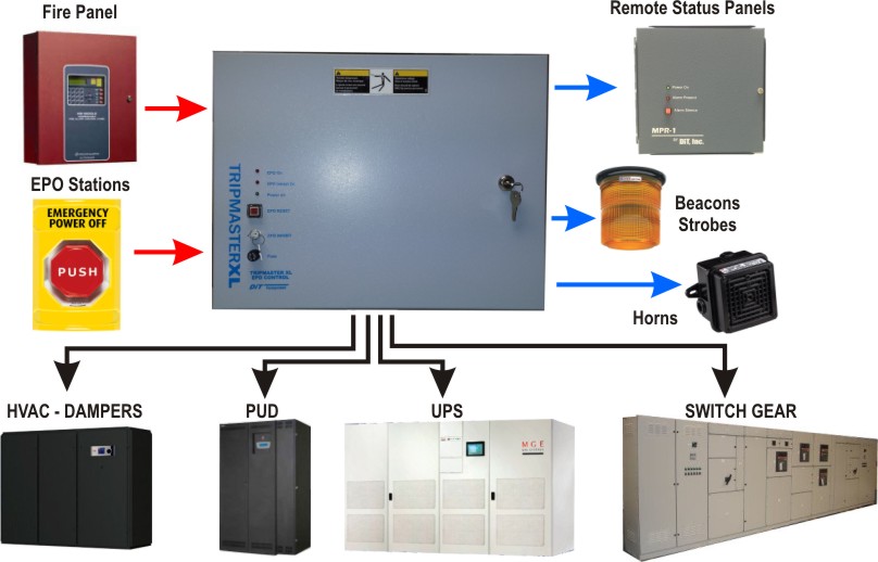
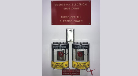
In industrial state electric operator duty is to operate the machinery and his duty is on the front of main panel board. Shunt trip breaker wiring diagram with epo button.

Installing A Shunt Trip In Abb Tmax Enclosed Circuit Breaker
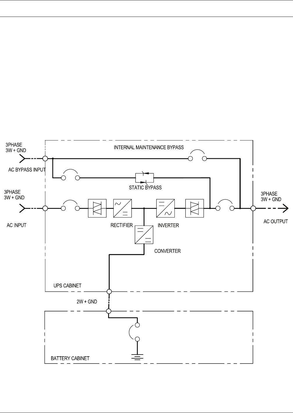
Epo shunt trip wiring diagram. Additionally no maintenance bypass switch is installed that would allow the epo to be defeated during routine. Shunt trip coil epo button push to close the traditional epo circuit is not fail safe however. Which is also known with the name of kill switch. Electrically from a remote location by application of control voltage to the accessory leads. Any such online diagram for the following variation would also be of interest. I could not find this anywhere on line.
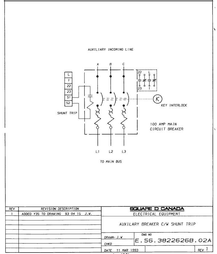
Shunt tr at electrical specifications. The epo box should have a set of connections for each device served. The shunt trip has coil clearing contacts that open when the voltage is applied so either momentary or maintained contacts can be used to initiate voltage. Several fault conditions can create a situation where the epo will not operate to shut off the circuit. Shunt trip device black wires maximum permissible voltage is 110 of rated for ac 125 for dc. The shunt trip allows the circuit breaker to be tripped table i.
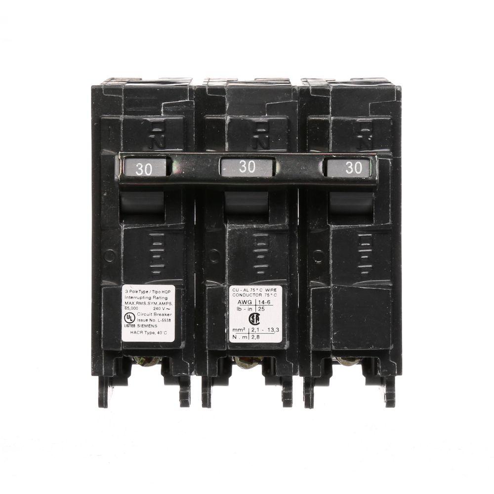
Shunt trip breaker wiring diagram this post is about the single wiring diagram of mccb shunt trip breaker. An eposhunt trip situation where there are multiple epo switches say three and the shunt trip coil circuit is powered from two phases of the same 480v circuit as powers the power circuit but is stepped down to 120v by transformer ahead of the epo switches and. Power circuits feeding shunt trip breakers are unidentified and unmonitored. In this post i am just tell you about wiring of single epo button with shunt trip mccb breaker. Sump pump installation diagram tripwire diagram shunt breaker wiring epo switch wiring diagramepo switch wiringshunt trip breakerplease provide a field wiriing diagram for connecting an epo in a data center to a trane model xxxxx so that the crac unit will shut down when the epo is engaged. Shunt trip accessories in qob are factory installed only and can not be added to an existing breaker.
Moreover the systems are rarely documented. The accessory terminals will accept 2 14 12 alcu. The breaker shunt trip coil is controlled by the emergency switch. You will run these wires to the shunt trip and it should work the same way. Thanks harry304e for the pertinent information. Loss of the epo circuit supply voltage loose wiring or conductors in the epo circuit a blown fuse in the epo circuit.
There are no shop drawings showing wiring diagrams location of devices and intended sequence of operation. Be it 24v 48v or 120v. The shunt trip breaker has to be selected and rated to match the box output voltage. In the diagram a mccb molded case circuit breaker shown which is wired for 3 phase system.
Gallery of Epo Shunt Trip Wiring Diagram