Data logging is only available if the ecu is attached for data logging. With sub harness.

Universal Programmable Ems 4 Wiring Harnesses Aem
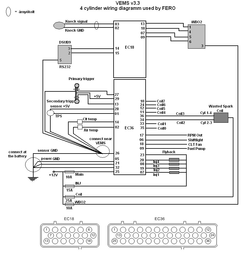
Ems stinger wiring diagram. Link to ems north america. See log controls wiring diagrams ecu connection diagram trigger and sync sensor connections hall sensor ems igniter wiring nos wiring diagram. Greyblue and black the ems stinger 4 ecu can use the original engine temp sensor on the engine. All systems have a built in map sensor which allows. The ems stinger 4424 engine management computer is programmed in real time via laptop. Here is a picture gallery about ems stinger wiring diagram complete with the description of the image please find the image you need.
The heart of the stinger is an embedded motorola microprocessor which has proven performance and reliability as in its bigger version the dual sport. Custom harness for the ems stinger made specific. It shows the components of the circuit as simplified shapes and the faculty and signal associates together with the devices. Diagram bacamajalah tips references. Ecu diagrams em tech series em140160180 em7080 motorsport and stinger motorsport 886068604860 stinger v4 motorsport r tech stinger s2r dualsport dualsport v6 ecus dualsport v5 ecus q and t series ecus ignition system diagrams coil ignition systems igbt ignitors sensor diagrams 4 channel egt modulelsu 49 o2 sensorspressure sensors. For map installed.
The data input rate from the ecu is set at 19200 baud which is compatible with the stinger ecu and some versions of the 8860 ecu. Jeep grand cherokee laredo jeep wrangler tj ford taurus trailer wiring diagram mustang restoration ford courier the dodge brothers 67 mustang diagram design. Ems stinger computer system. Stinger sets the bar for badass sound performance and is the go to brand for car audio enthusiasts competitors and car tuners across the globe. Stinger has everything a true audiophile and passionate accessorizer needs to upgrade a vehicles sound or infotainment system or upfit your boat sxs or car with the latest accessories. Just wondering if anyone has a wiring diagram for a ems stinger ecu for the rb30 or know where i can get one.
Ems stinger wiring diagram wiring diagram is a simplified within acceptable limits pictorial representation of an electrical circuit. The stinger 4 system provides flexible data logging capabilities to assist in gaining the maximum efficiency from an engine. It controls both fuel and sequential ignition. Ems stinger 8860 6860 and 4860 ecus. It is important that the engine temperature readings be reliable and accurate. I am in the process of makin.
The calibration can also be saved as a file and reused on other ems ecus. Rooftop refrigerator wire chevy rooftops refrigerators cord cable. You can calibrate the sensor to the ecu. Ems stinger wiring diagram. Ems stinger 4424 wiring diagram ems stinger 4424 v4 wiring intended for ems stinger wiring diagram image size 618 x 799 px and to view image details please click the image. The ems serial race technology interface connects between an ems stinger ecu and either a data logger or a dashboard enabling monitoring of all the data channels.
Gallery of Ems Stinger Wiring Diagram