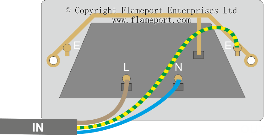
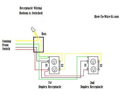
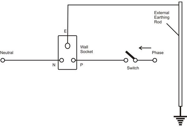
In the wiring diagram above a hot and a neutral enter the single pole switch box. You should switch off electrical power from the mains to avoid electrocution.
Wall Socket Wiring Diagram Swichw 2011 Rmnddesign Nl
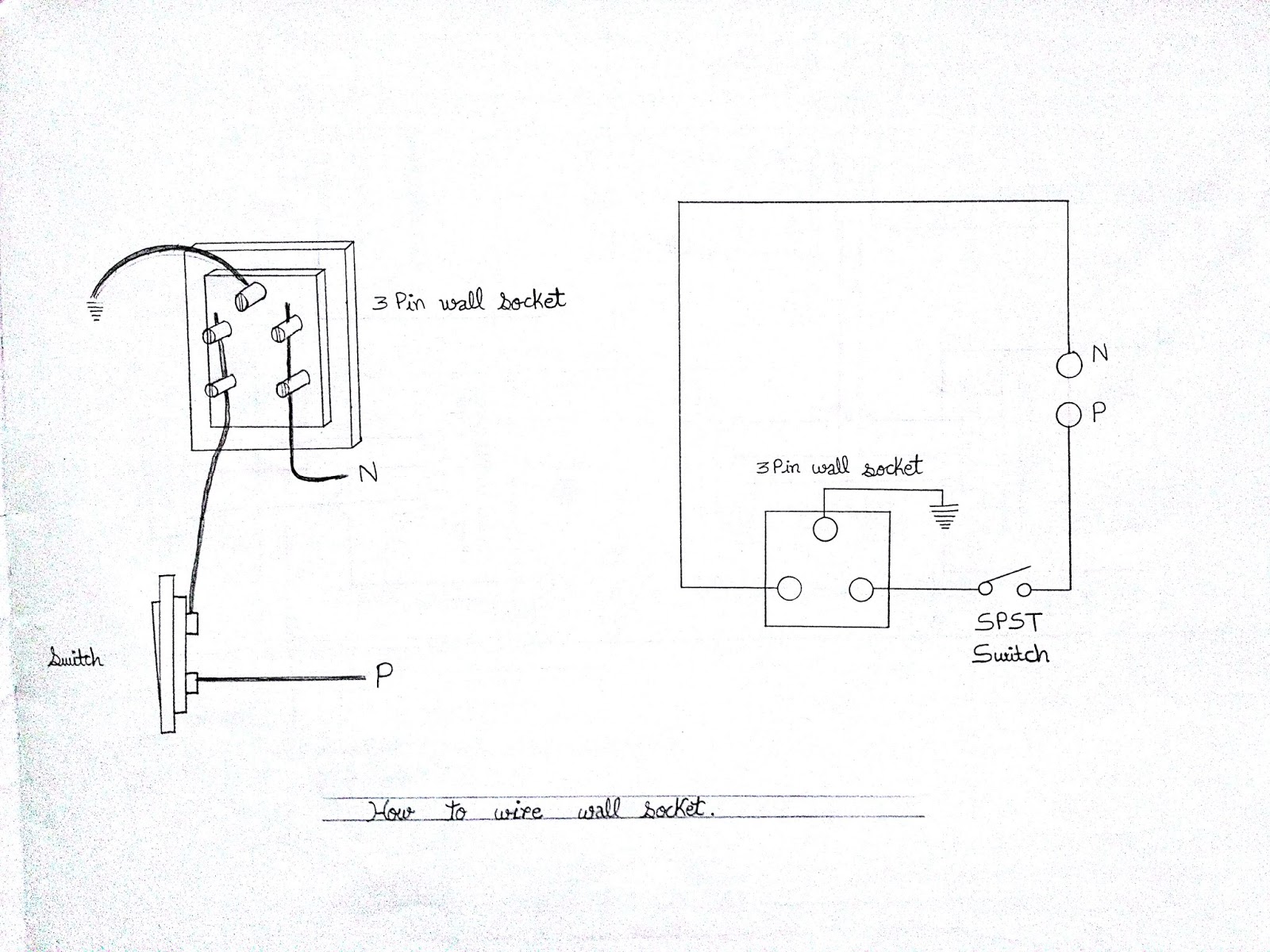
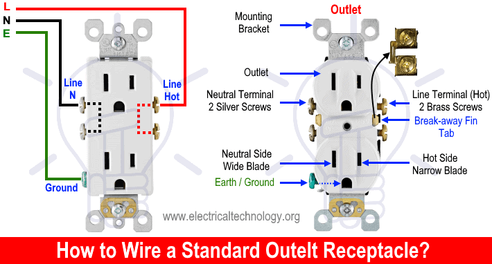
Electrical socket wiring diagram. The kitchen electric range may also be found to have a 3 wire or 4 wire cord or 220 volt outlet which will require proper electrical connections and wiring as found in the diagrams and instructions. Electrical outlet boxes can have numerous nm cables going in and out. Switch off the mains. The source is at the outlet and a switch loop is added to a new switch. Diagrams shown on this page are simplified for clarity. A grounded contact at the bottom center is crescent shaped.
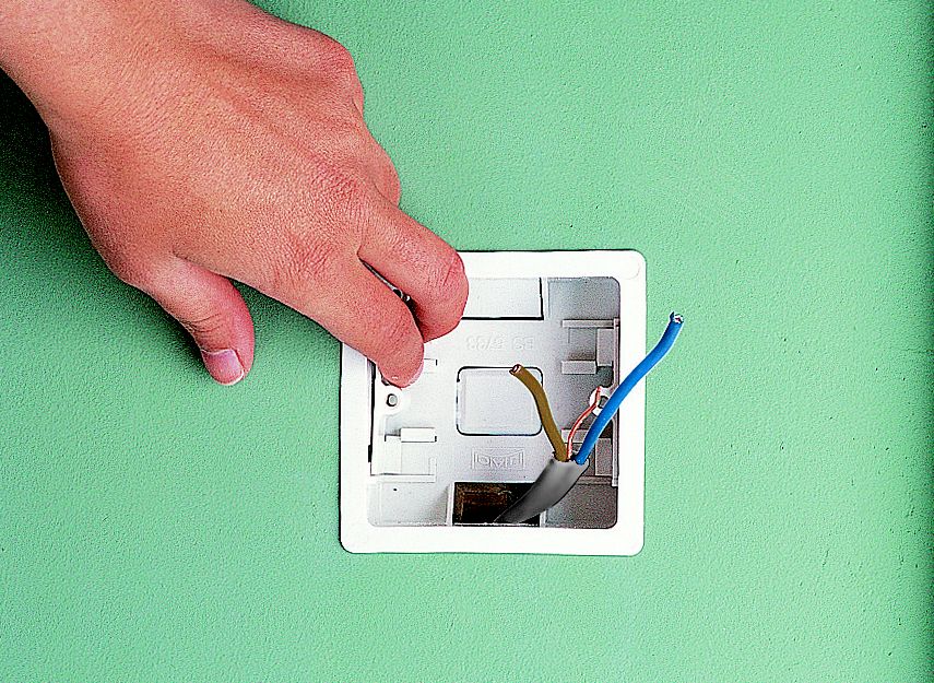
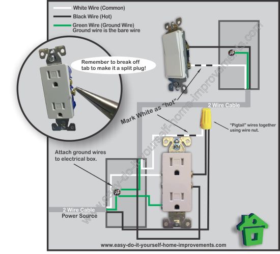
Wiring a gfci outlet with combo switch outlet receptacle light switch. Wiring diagram for multiple outlets. This repeats until the end of the chain. One cant be too careful. Dont use this receptacle when no ground wire is available. All wires are spliced to a pigtail which is connected to each device separate from all the others in the row.
If not the arrangement wont work as it ought to be. This is a standard 15 amp 120 volt wall receptacle outlet wiring diagram. From there a 3 conductor cable is installed to a switched electrical receptacle outlet. The black wire from the switch connects to the hot on the receptacle. Each component ought to be placed and connected with other parts in specific manner. This wiring allows for source voltage at each outlet independent of the others in the circuit.
The hot source wire is removed from the receptacle and spliced to the red wire running to the switch. How to wire an electrical outlet. In the diagram below a 2 wire nm cable supplies line voltage from the electrical panel to the first receptacle outlet box. So when the switch is off all hot parts of the lamp are well protected. This wiring diagram illustrates adding wiring for a light switch to control an existing wall outlet. The threaded socket is the neutral.
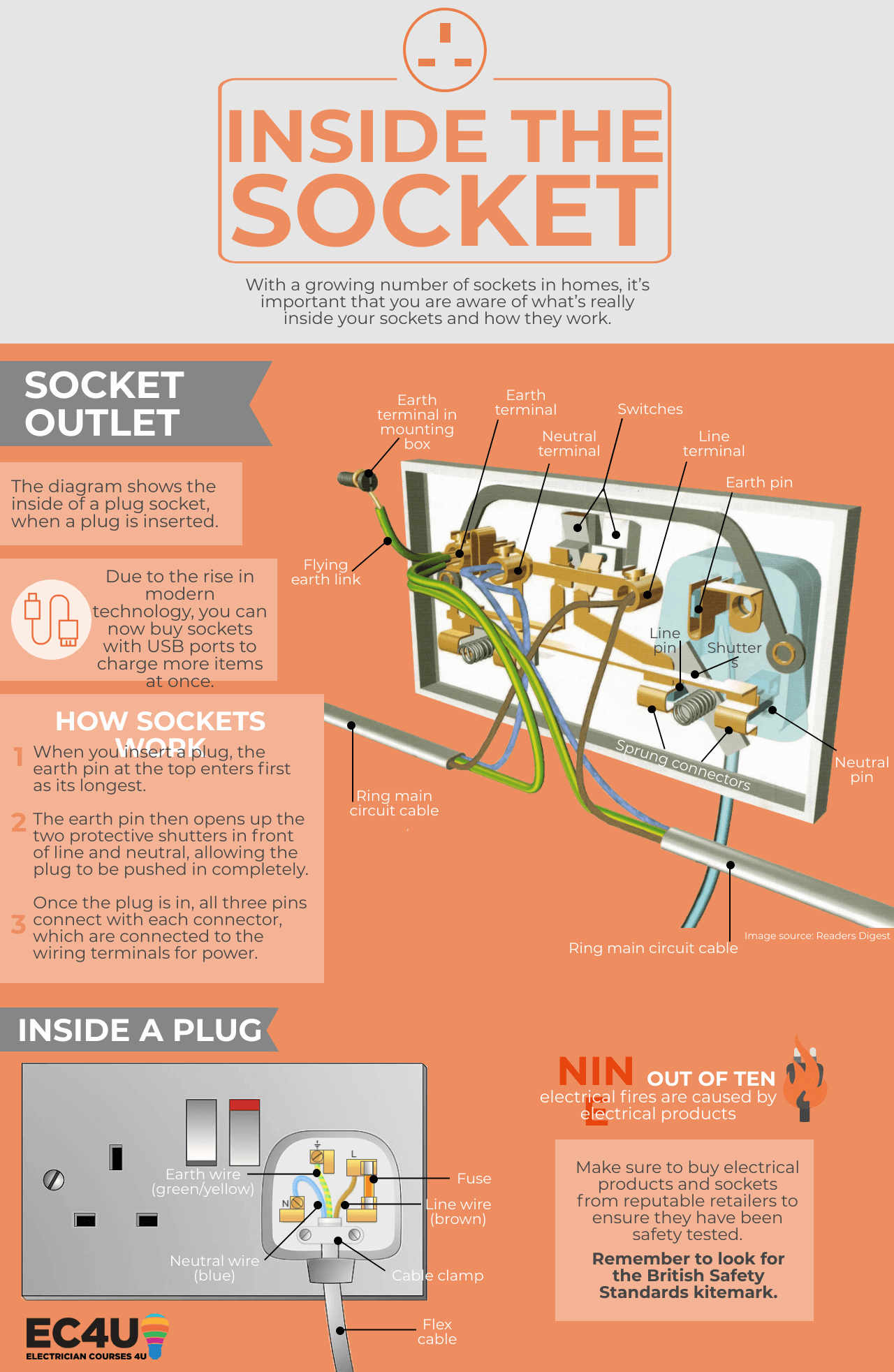
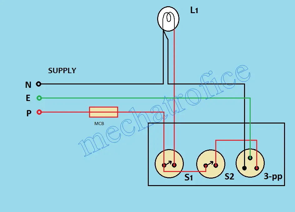
Light socket wiring diagram australian light socket wiring diagram clipsal light socket wiring diagram australia deta light socket wiring diagram every electric arrangement is made up of various distinct pieces. In this gfci outlet wiring and installation diagram the combo switch outlet spst single way switch and ordinary outlet is connected to the load side of gfci. Most arc welders require a dedicated electrical circuit and 220 volt outlet that is sized according to the specifications of the welder as. This diagram shows the wiring for multiple receptacles in an arrangement that connects each individually to the source. The long slot on the left is the neutral contact and the short slot is the hot contact. See actual switch box wiring diagram.
The black wire line and white neutral connect to the receptacle terminals and another 2 wire nm that travels to the next receptacle. And when the switch is on only the tab at the bottom of the socket is hot but if the wiring is reversed and the power goes to the threaded socket the threaded socket is always hot whether the switch is on or off. Run the cable from the circuit breaker to the location of the electrical outlet. Your cable should be long enough to reach each socket. This is a polarized device. A two conductor cable is installed from the switched outlet to feed an outlet that is live at all times.
Wiring a grounded duplex receptacle outlet.
Gallery of Electrical Socket Wiring Diagram