A wiring diagram is a streamlined conventional photographic representation of an electrical circuit. Electrical standards direct line dol starter.

Three Phase Dol Starter Wiring Diagram لم يسبق له مثيل الصور
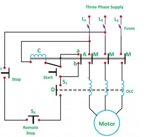
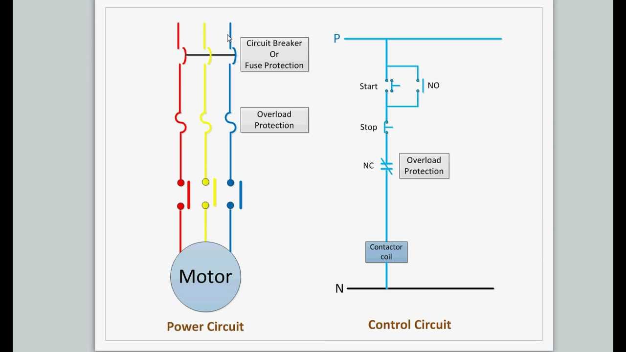
Dol starter wiring diagram pdf. A direct online starter consits of two buttons a green button for starting and a red for stopping purpose of the motor. The wiring of direct on line control circuit starter is following. Motor starter wiring diagram pdf gallery allen bradley smc 3 wiring diagram new fine allen bradley motor. All other control and power connections have to be made by the installer. Assortment of 3 phase motor starter wiring diagram pdf. The direct on line motor starter dol is designed to switch a single or three phase induction motor at rated voltage.
These two buttons ie. 13 17 with a flying lead to be connected to overload terminal 95. What is direct line starter its theory of starting circuit globe. A2 14 18. It comprises an enclosure in steel or plastic a contactor start contact link wires and stop start buttons. The connection of contactor can be done among relay coil supply voltage as well as thermal overload.
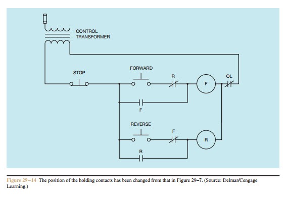
Green and red or start and stop buttons control the contacts. It shows the elements of the circuit as streamlined shapes and the power and signal links in between the tools. 1 the following links are pre fitted to the starter. Wiring diagrams vs line diagrams most of the diagrams in this book are shown in two ways. Electromagnetic contactor which can be opened by the thermal overload relay under fault conditions. There is a wiring diagram and adjacent to it a line diagram line diagrams are included because their use is becoming more widespread and we believe it is advantageous to learn to use them.
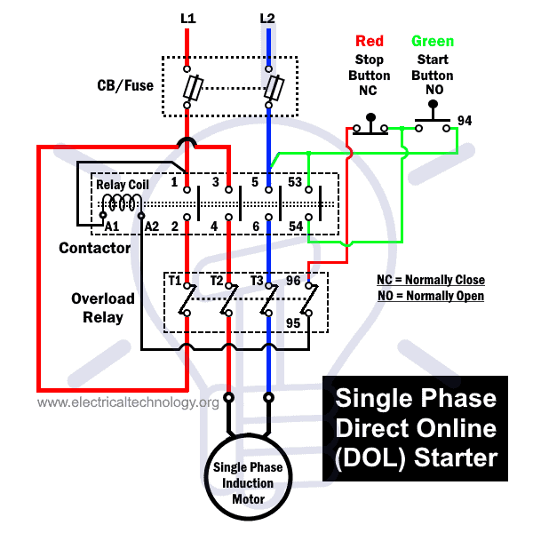
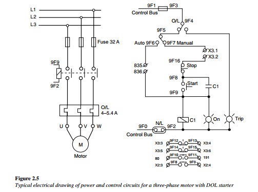
The simplest form of motor starter for the induction motor is the direct on line starter. The l1 contactor is connected from normally open no to r phase using mccb. In the below dol starter wiring diagram i shown a molded case circuit breaker a magnetic contactor normally open push button normally close push button switch thermal overload relay motor trip indicator and 3 phase motor. All connection i shown with complete guide. The direct on line motor starter dol consist a mccb or circuit breaker contactor and an overload relay for protection. Wiring of the direct on line dol motor starter 1 three phase supply 230volt coil see wiring diagram.
A wiring diagram is a streamlined standard pictorial representation of an electric circuit. 1 22kw motor with a flc of 5 amps at 415volts. The wiring diagram for a dol stater is shown below. Assortment of motor starter wiring diagram pdf. Dol starter control diagram three phase. In the above three phase dol starter wiring diagram.
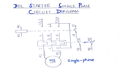
The dol starter comprises of an mccb or circuit breaker contactor and an overload relay for protection. Single phase motor control wiring diagram electrical engineering. It shows the parts of the circuit as simplified shapes and also the power and also signal links in between the tools. The thermal overload is supplied as a separate item.
Gallery of Dol Starter Wiring Diagram Pdf