2 gang rotary twin dimmer switch. 01268 563405 uk sales fax.

Single Pole Light Switch Wiring Diagram Single Pole Dimmer
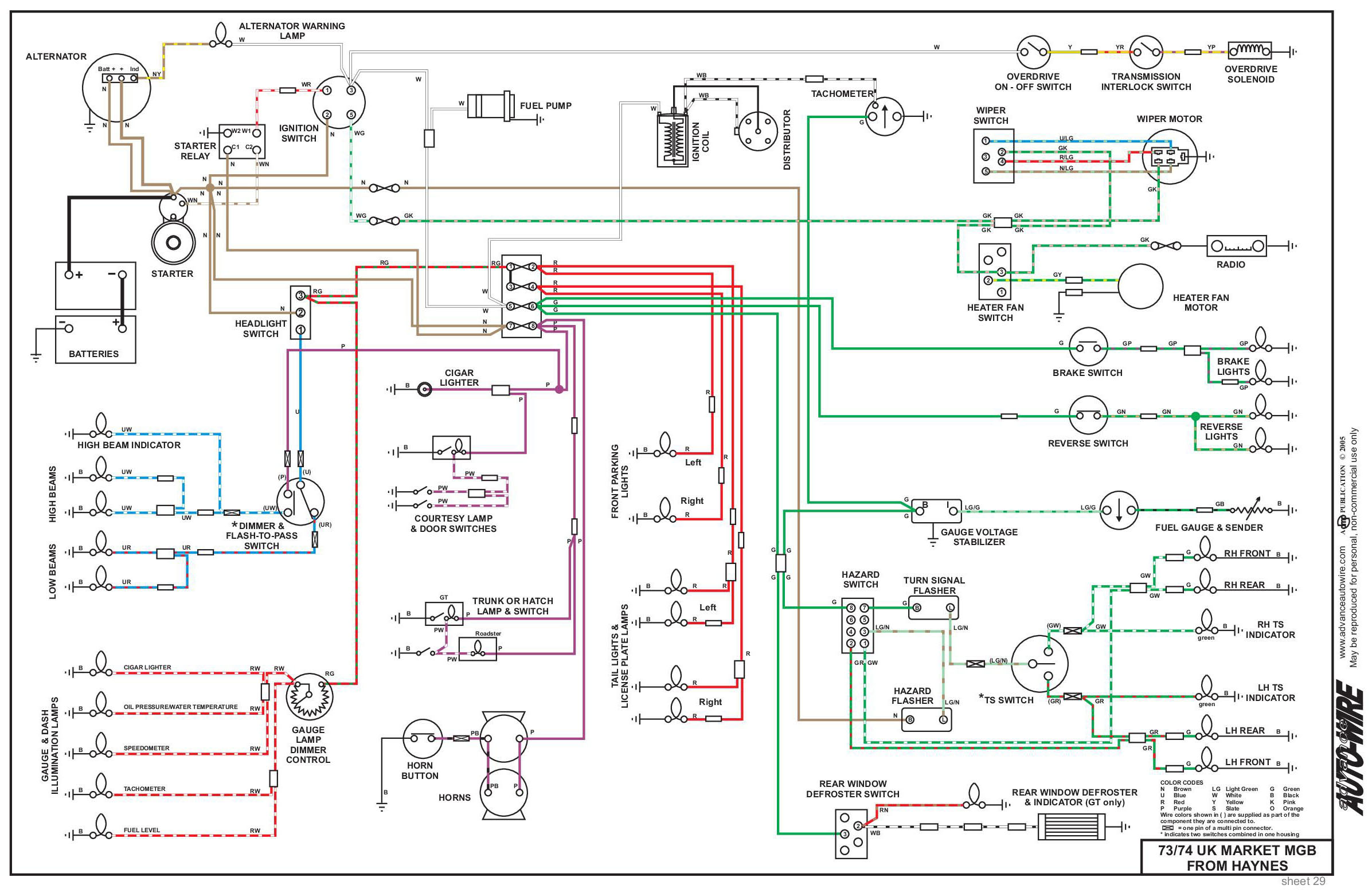
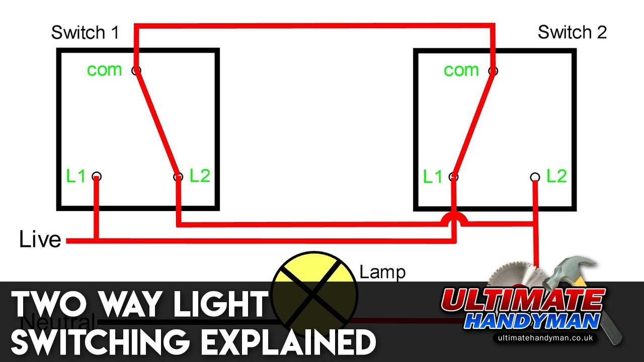
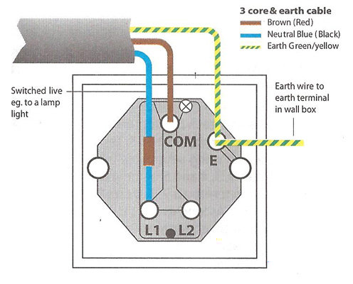
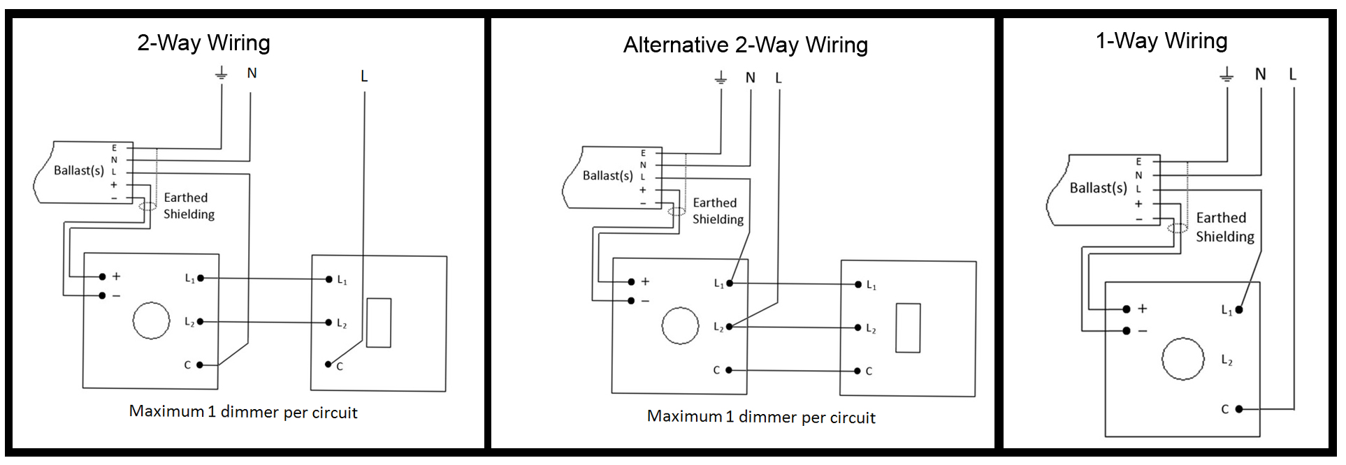
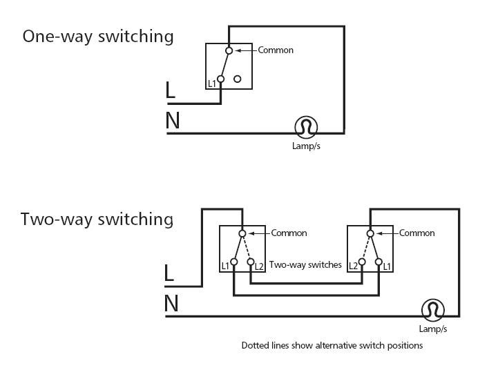
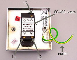
Dimmer switch wiring diagram uk. The black line wire connects to the common terminal of the 3 way dimmer. See below links to various images of wiring diagrams for installing varilight products. Dimmer figure 1 typical one way switch circuit load dimmer 2 way com switch l1 l2 l from mains supply n mk electric novar eds ltd the arnold centre paycocke road basildon essex ss14 3ea. A 3 wire nm connects the travelers of the dimmer to the travelers of the 3 way switch. Many manufacturers are now producing dimmer switches that can be used for either single pole or 3 way switches. In the diagram below a 2 wire nm cable supplies power from the panel to the dimmer box.
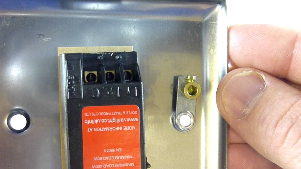
If you are replacing an existing 3 way switch. Traveler wires are interchangeable on each switch. The unit below is suitable for a 40w to 300w. Remove your old switch and copy the wiring configuration for the dimmer. 44 01268 563000 fax. 44 0 1268 563360international email.
Most are remote or manually controlled. There are also remote control dimmer switch units available easily replacing a standard switch or existing dimmer switch. The wires fitted in the common terminal of the old switch should be fitted into the c terminal of the dimmerswitch. Touch dimmer diagrams are for the following ranges v pro ir v pro multi point touch and remote and v pro eclique2. Remote operation can take place from up to 15m away and the last light level is stored in the memory. Remove your old switch and copy the wiring configuration for your dimmerswitch.
When replacing an existing 3 way switch take note of how the existing switch is wired before you remove the wiring then refer to your notes to help you wire the new 3 way dimmer switch. Figures 3 and 4 which show typical 2 way circuits.
Gallery of Dimmer Switch Wiring Diagram Uk