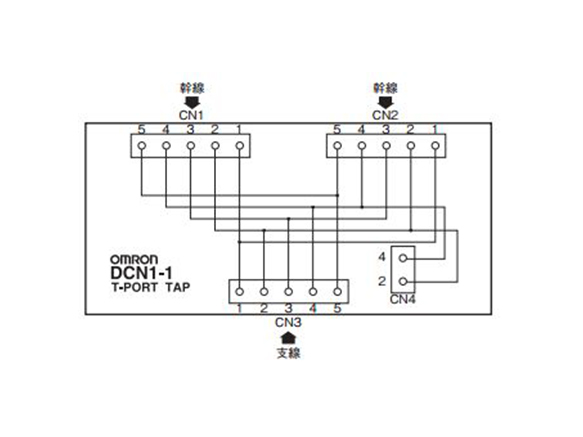
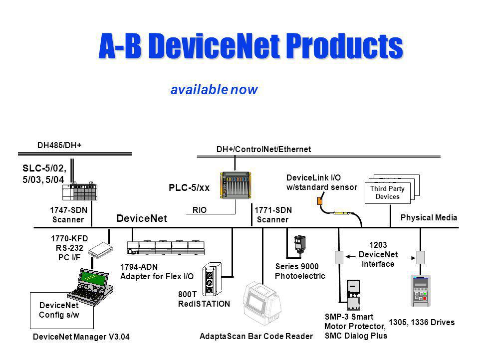
62 wiring diagram the devicenet interface is connected to the actuator terminal board by internal wiring as shown below. 11212011 123737 pm.

Kx 6167 Index 40 Basic Circuit Circuit Diagram Seekiccom
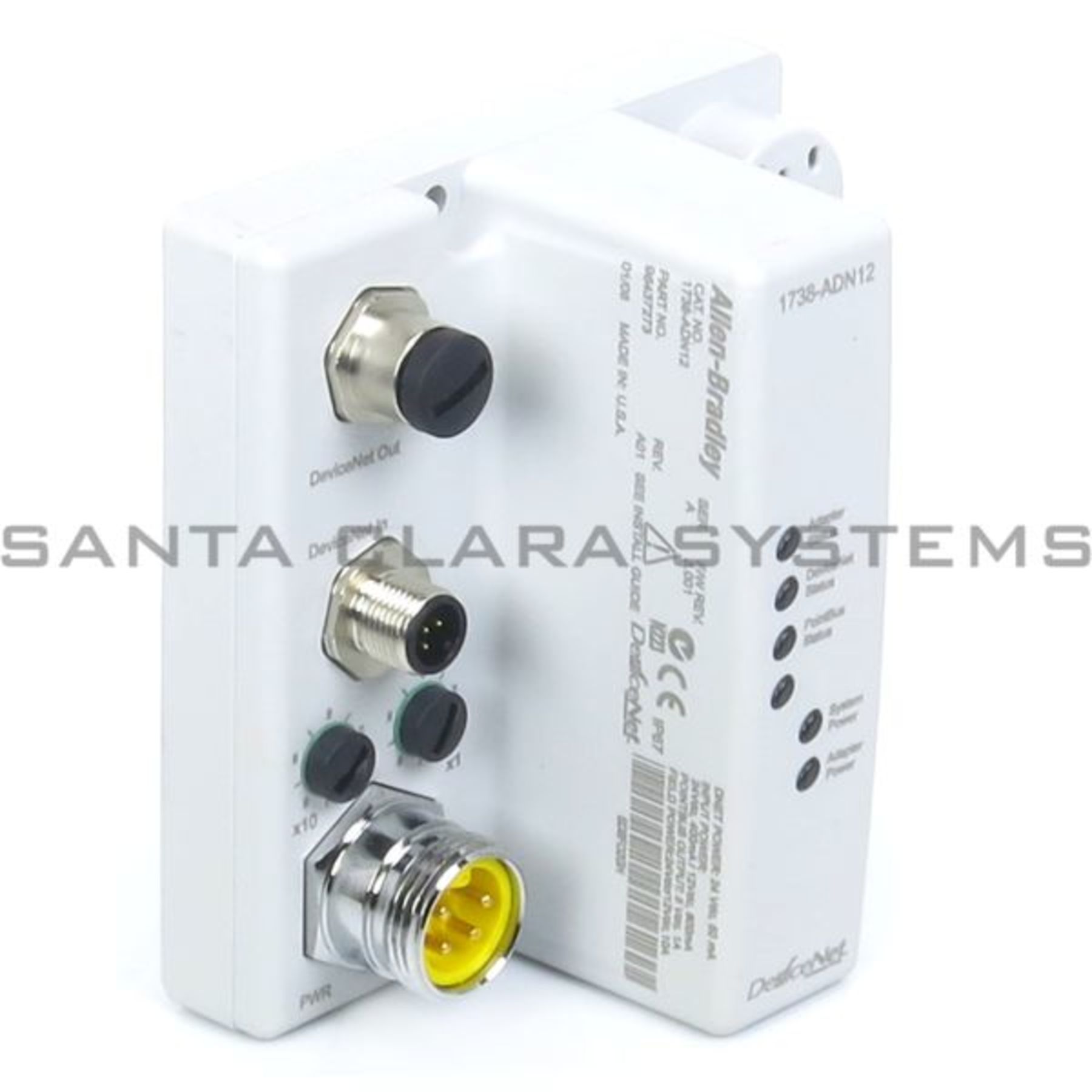
Devicenet wiring diagram. Appendix b shows the dimensions of the devicenet devices. Figure 22 wiring diagram 24v dc inputrelay output cat. The steps in this chapter describe the basic tasks involved in setting up a network. Drop line the network cable between the trunk and nodes. Optional module devicenet interface connector h hw mode devicenet line shield canh canv white red modstat module status led as defined in spec. The wiring diagram for each specific type is located on the right side of the device housing.
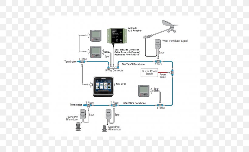
Each drop line may be no longer than 6 meters. Devicenet planning and installation manual author. Phoenix contact gmbh co. 3 devicenet adaptation for cip chapter 7. Section 3 describes the devicenet communications power supply methods and provides a step by step procedure to determine the ideal location for the power supply or power supplies appendix a provides lists of omrons devicenet devices. Devicenet uses a trunk line and drop line topology to connect nodes for communication.
Devicenet planning and installation manual created date. For information on this topic see page before you begin 1 2 set up a devicenet network 1 4 understand the. It is usually a thick cable. Dsa wiring diagrams figure 22 through figure 24 shows typical wiring diagrams for three versions of the dsa module. Tr terminating resistor component description trunk line the network cable between terminators. 100 dny42r shown dnet 24v red can h white can l blue dnet 24v black 4 3 2 1.
Whats in this chapter this chapter introduces the devicenet cable system and provides a brief overview of how to set up a devicenet network efficiently. Here is an example.
Gallery of Devicenet Wiring Diagram