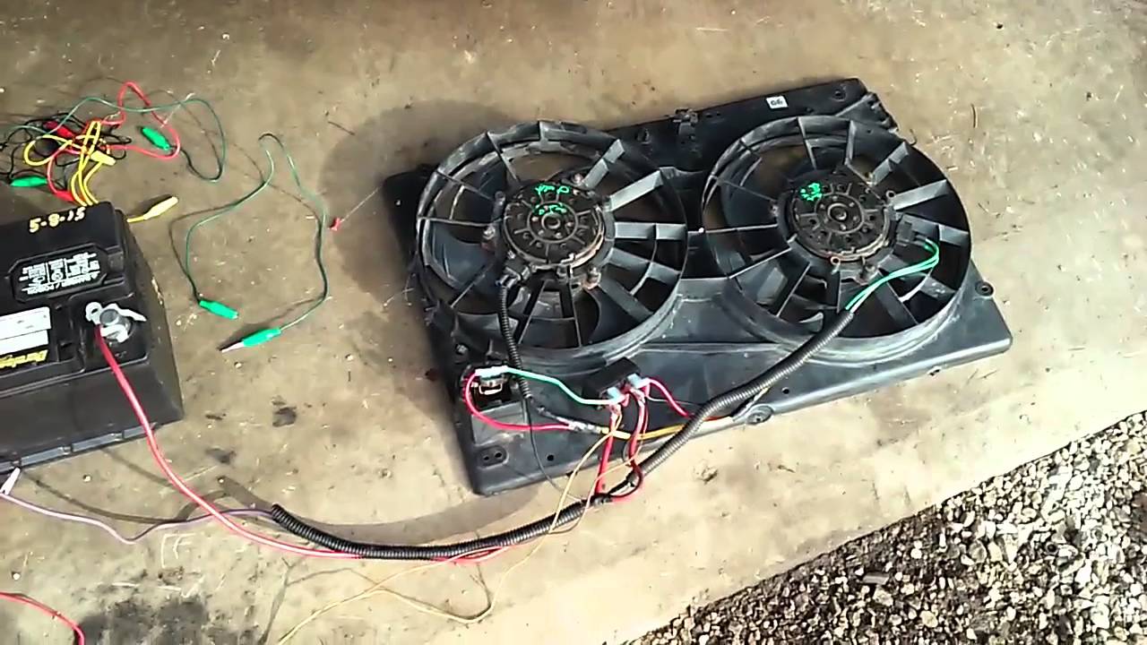
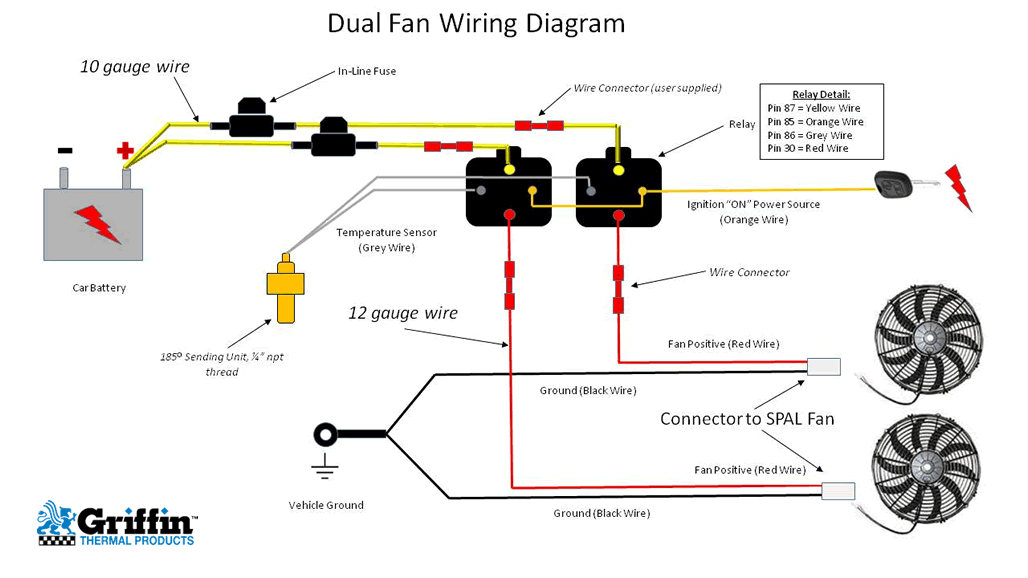
Reference diagrams 78onpage 2 the electric fan assembly is built using a high output two speed motor. Dual fan configuration orange wire.
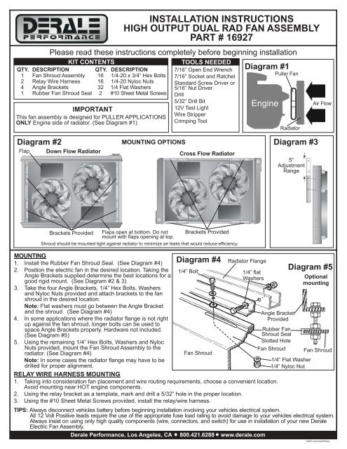
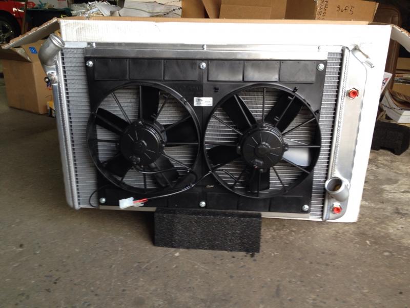
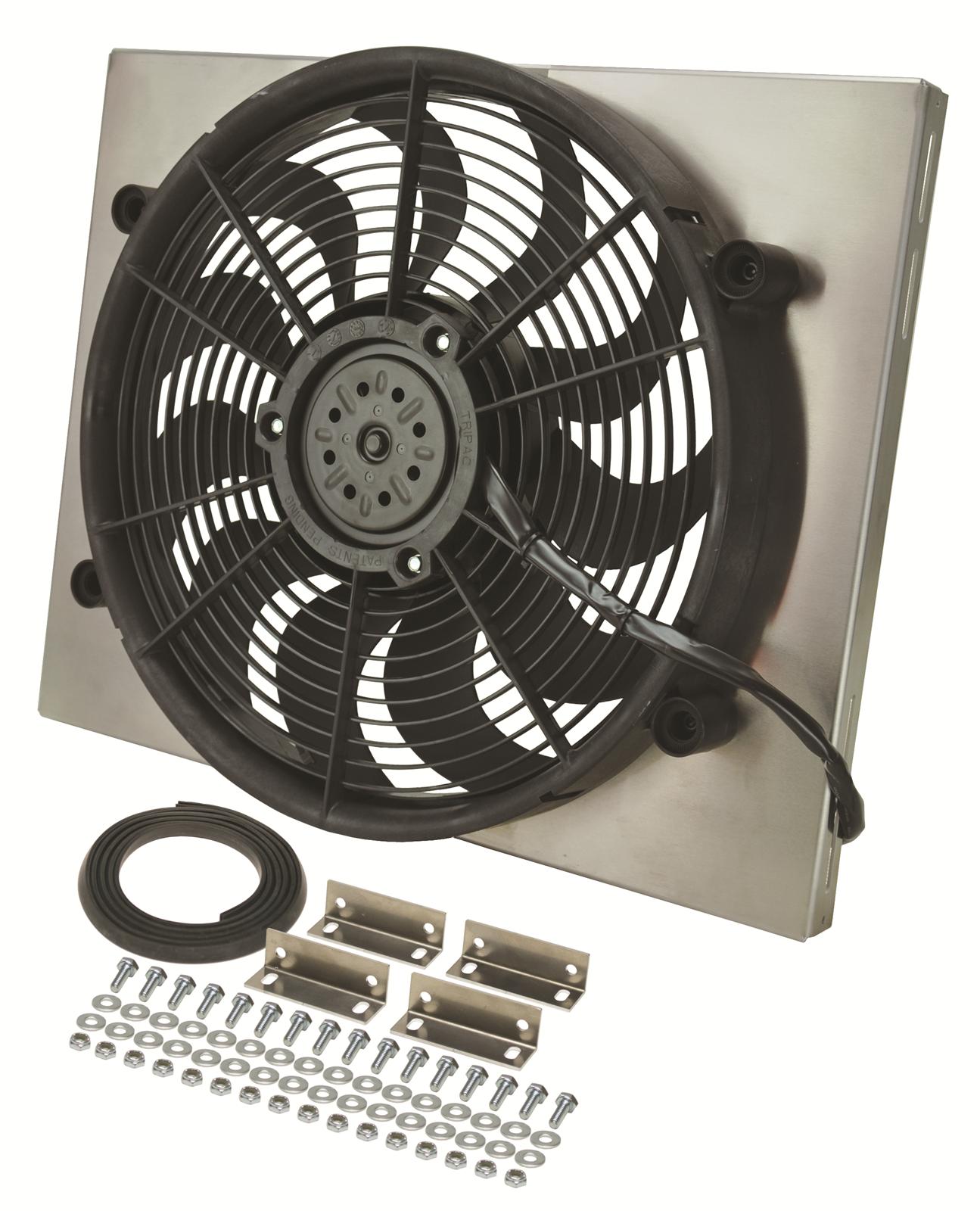
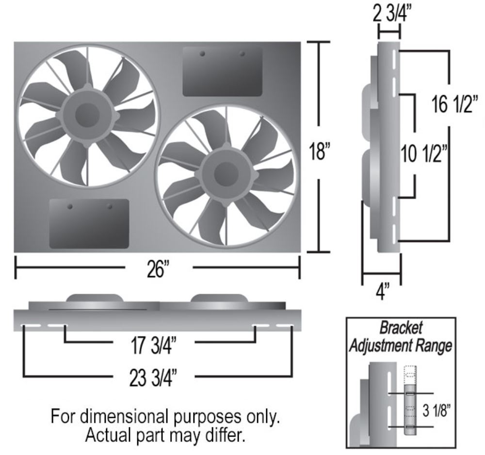
Installation Instructions High Output Dual Rad Fan Assembly
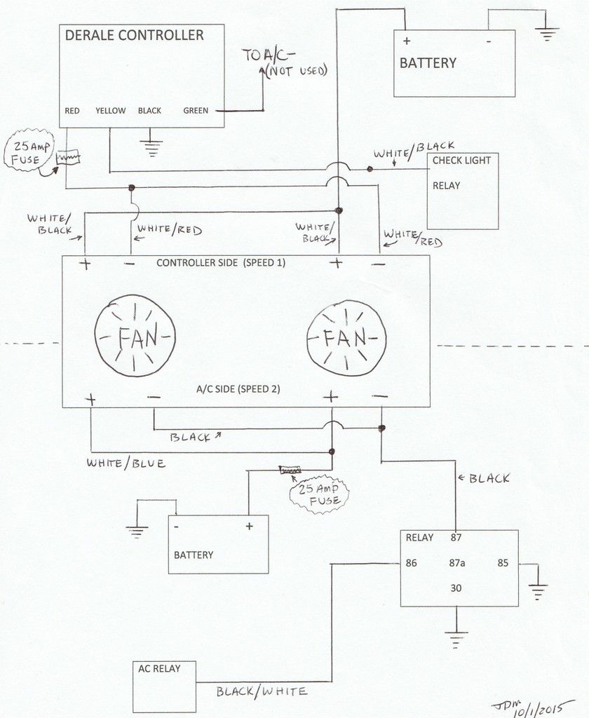
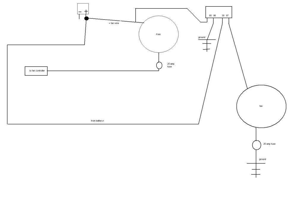
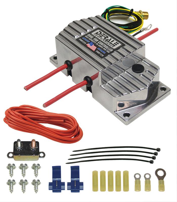
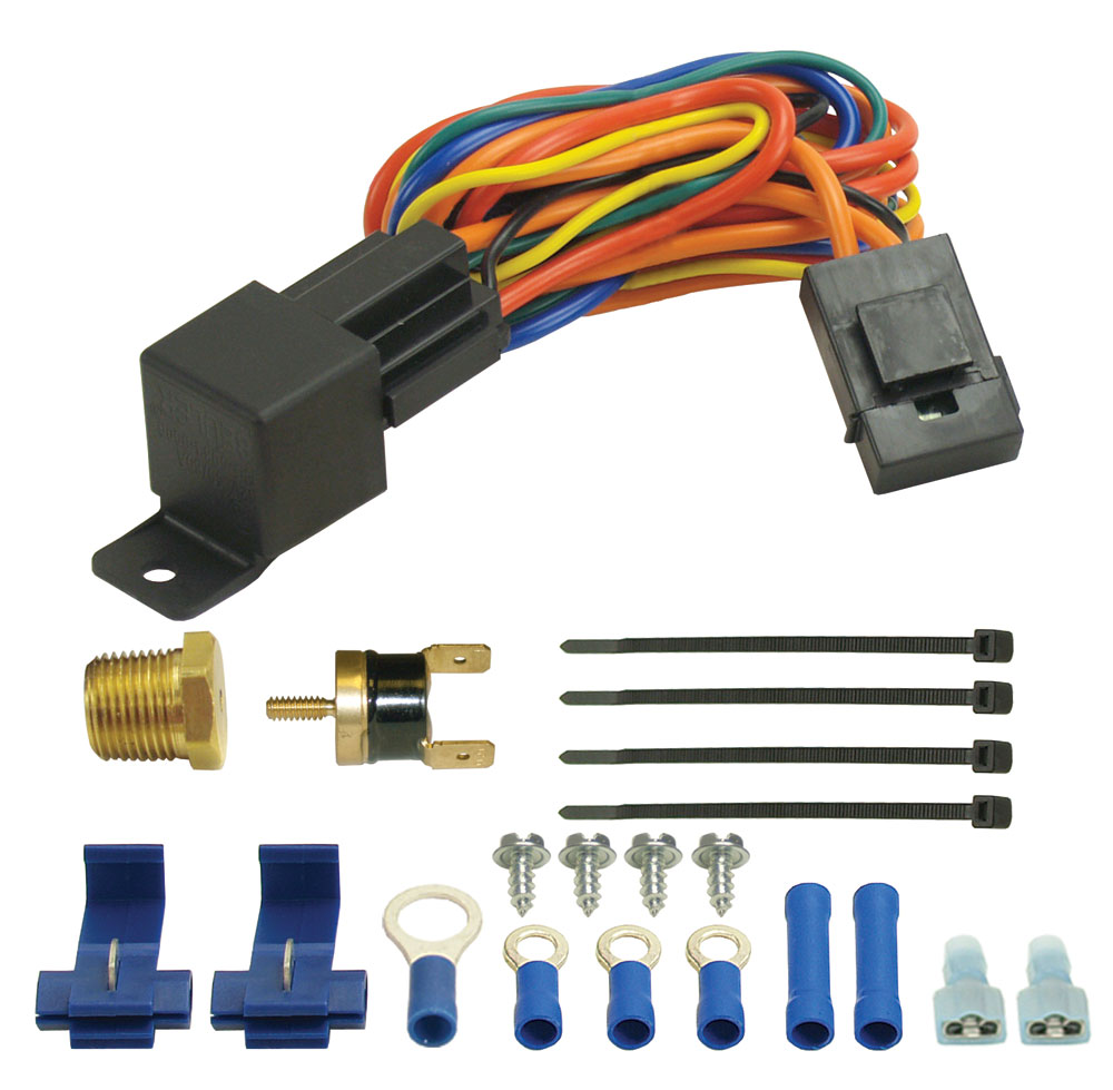
Derale dual fan wiring diagram. Heres some similar controllers. The derale high amperage adjustable dual fan controller is designed to operate two electric fans at different activating temperatures. Diagram 2 wiring before starting disconnect the negative cable on the vehicles battery. Description 1 fan shroud assembly 4 angle brackets 1 rubber fan shroud seal qty. This one is a schurz. This is based on the draw from the fans if the fans are larger and draw more than 15 amps each its recommended to install a second relay kit as shown below.
Single stage electric fan. If fan started reattach the green wire to the proper wire on the ac clutch or manual switch. With dual cooling fans there are two methods for wiring up the relay kit. View and download derale 16739 installation instructions online. Terminal on the battery. High output dual rad fan assembly part 16927 kit contents qty.
Wiring dual cooling fans. Diagram 4 diagram 3 30amp fuse red wire battery power 12v black wire chassis ground green wire optional ac. Electric fan should start immediately. 16739 thermostat pdf manual download. Trouble shooting qa diagram 3 relay red yellow black green to 12v switched ignition to ground chassis override circuit loose red wire positive battery negative. Fan 1 is designed to activate at the desired adjusted temperature 150 240f.
If you choose to operate the fan using both speeds two switching devices or a derale dual fan controller part 16788 or 16789 is recommended. Filmed this while filming my last vlog and wanted to do a dedicated diy on how to wire an electronic fan controller. Fan 1 orange wire.
Gallery of Derale Dual Fan Wiring Diagram