This symbol identifies a note about a situation where damage to a. More insulation is required and the voltage appearing between windings and core will be equal to full line voltage in case of earth fault on one phase.

Typical Connection Diagrams Three Phase Motors Y Start
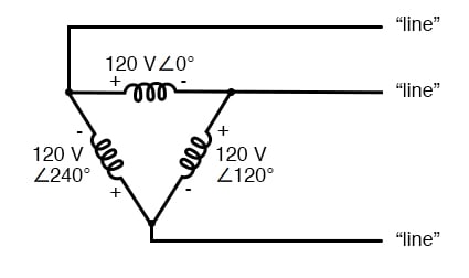
Delta wiring diagram. The three phase power is connected in the delta configuration and the center point of one phase is grounded. The name is given due to the shapes of the circuit diagrams which look respectively like the letter y and the greek capital letter which resembles a triangle. This symbol identifies a note about a situation where damage to a. In the uk the wye diagram is also known as a star. Due to the absence of neutral point it is not suitable for three phase four wire system. Three phase three wire δ connection has no common.
It is called orange leg because the wire is color coded orange. Motors loads are commonly connected to phases a b and c while single phase loads are connected to either phase a or c and to neutral. This creates both a split phase single phase supply l1 or l2 to neutral on diagram at right and three phase l1 l2 l3 at right. Disadvantages of delta delta transformer connection. Wellborn collection of wye start delta run motor wiring diagram. A four wire delta 4wd electrical service is a three phase delta service with a center tap on one of the transformer windings to create a neutral for single phase loads.
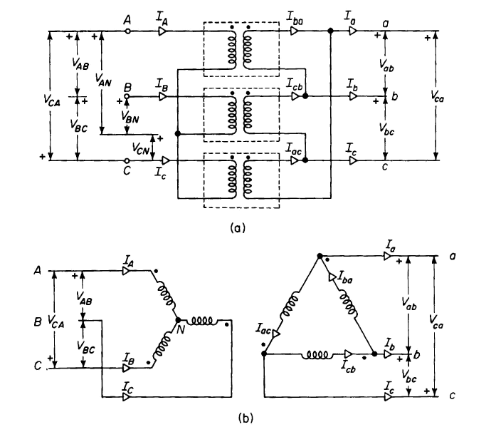
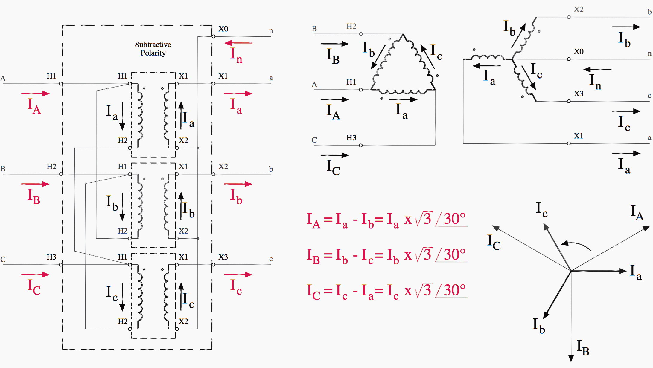
Delta controls has written wiring and installation guidelines to provide its partners with a primary source of recommended practices for wiring power inputs and outputs and networks for delta controls products. The wye and delta also described as y delta wye delta is a mathematical technique to simplify the analysis of an electrical network. Delta or mesh connection δ system is also known as three phase three wire system 3 phase 3 wire and it is the most preferred system for ac power transmission while for distribution star connection is generally used. The dashed lines indicate the transformer outlines. A wiring diagram is a simplified conventional photographic depiction of an electrical circuit. December 15 2018 by larry a.
Take close notice of the polarity for each winding in the figure below. Another configuration is known as the delta for its geometric resemblance to the greek letter of the same name δ. Delta controls has written wiring and installation guidelines to provide its partners with a primary source of recommended practices for wiring power inputs and outputs and networks for delta controls products. Figure 2 deltadelta transformer connections click to expand diagram the connection diagram on the left shows how a deltadelta connection can be made either with three single phase transformers or with one three phase transformer. It shows the parts of the circuit as streamlined forms as well as the power as well as signal links between the gadgets.
Gallery of Delta Wiring Diagram