It differs from the centralized control system wherein a single controller at central location handles the control function but in dcs each process element or machine. View online or download dcs rgs 364gl installation manual use and care manual.
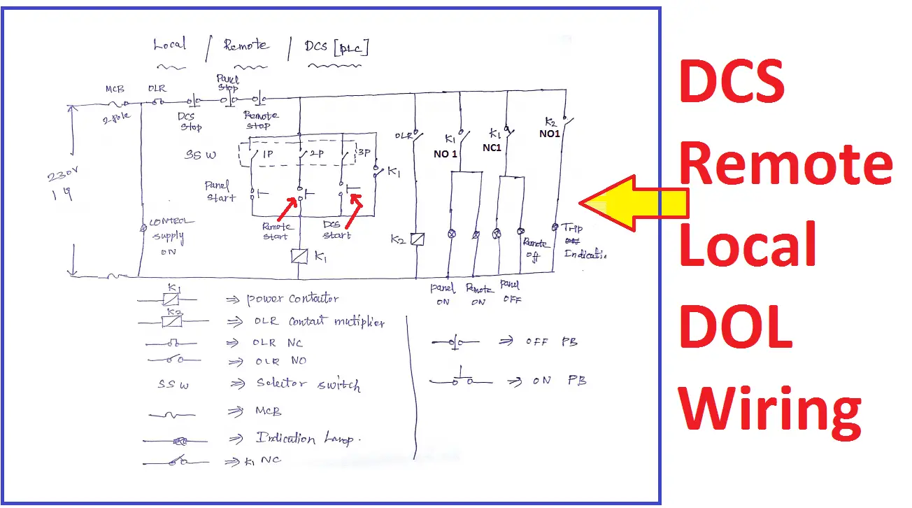
Plc Dcs Start Stop Wiring Diagram Electrical4u
Dcs wiring diagram. Call us on 18889367872. Enter your appliances product code or model number below. Otherwise do as tom suggests. Ron just wire up dcs as usual without any changes in your layout wiring at present. The product code is a 5 or 6 digit number printed on the serial label attached to your appliance. Enter model number product code.
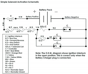
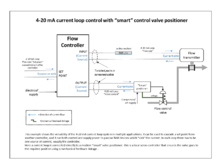
Devices can also be actuators such as valves. In binary codes and the same will be communicated to processor card. Once the main cables are connected to the analog input card via internal wiring and it converts the 4 20ma which is coming from field devices into equivalent digital signal ie. User guides and manuals download the user guide or manual for your outdoor or indoor product here. E z go dcs wiring diagram red red redwht redyel ornred yel red orn grn yel blu red redyel red yelwht run rev 1 2 3 4 5 6 7 8 9 10 f1 f2 b b m direction selector switch reversing horn controller key switch ignition interlock charger socket solenoid traction motor wht wht blk blk grnblk grnblk. A distributed control system dcs is a specially designed automated control system that consists of geographically distributed control elements over the plant or control area.
The wires carry electrical power to a device. In a conventional distributed control system dcs two wires are used to connect to a device. The devices may be instruments for measuring temperature or pressure. Dcs rgs 364gl pdf user manuals. Our experienced customer care team are available 24 hours 7 days a week. Welcome to support for dcs outdoor appliances.
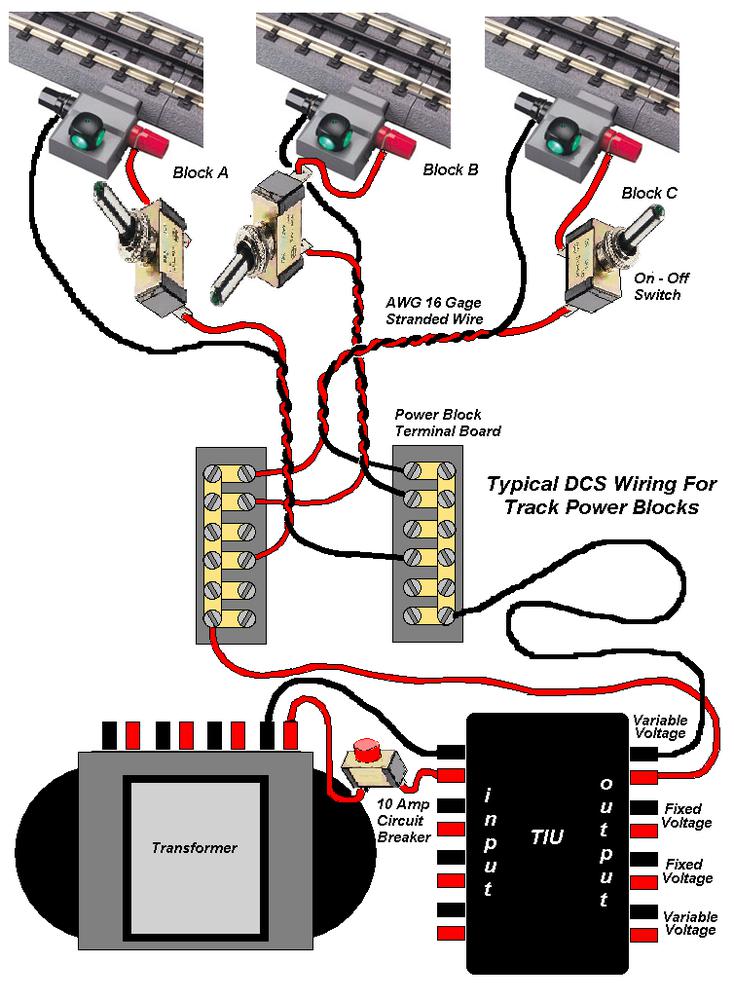
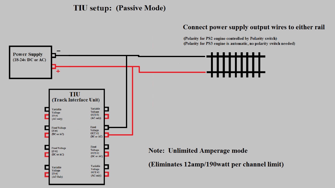
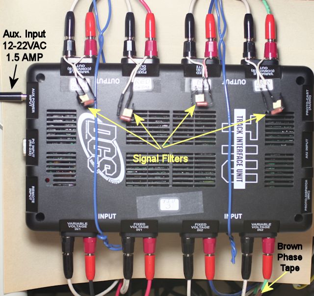
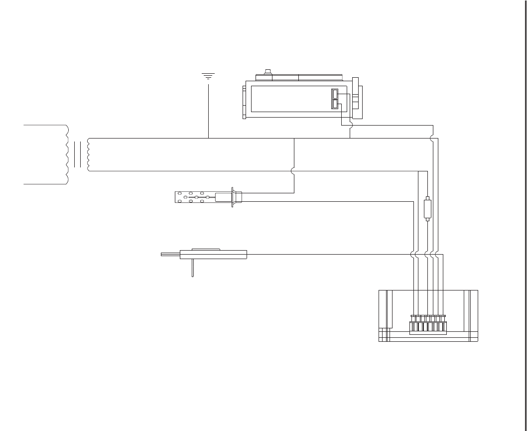
So we use internal wiring to route these main cablesfield devices from marshalling to system cabinet. More details book a service assistance and complete servicing for all dcs outdoor and indoor. With dcs you are sending both power and a control signal thru the track as a result you want all tracks to recv the signal at about the same time with the same strength. Shared wiring for powering devices and carrying signals between devices. Wiring diagrams of plc and dcs systems di do ai ao x liquid level control using flow loop control systems since liquid level can only change in a vessel if there is an imbalance of inlet and outlet flow rates would this system be practical to achieve stea.
Gallery of Dcs Wiring Diagram


-v1.jpg)