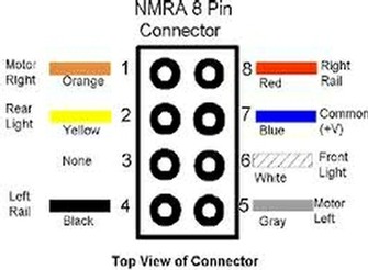
The 8 pin version is known as the medium size and is the most common standard dcc connector used in ho and oo locomotives. 8 pin plug with color code.
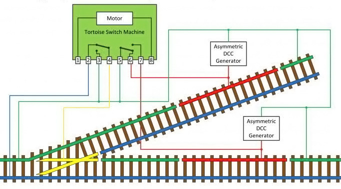
Bitswitch Asymmetrical And Dc Brake Generators News Amp Resources
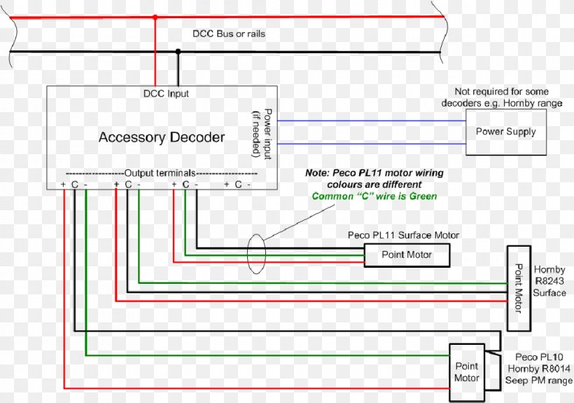
Dcc decoder wiring diagram. The blue wire is a common wire for all of the lights. Switch and contact position may also vary with time due to product evolution. Wiring for dcc isnt as complicated as some would have you believe but it is a very important component to the entire digital command control experience. Locomotive makers of rarely ever follow the dcc wiring standards for wire colour when making their locomotives even if they are adding dcc ready sockets. To accompany the tutorial weve produced a pdf containing a series of basic wiring diagrams to help with the installation process. Low voltage bulbs or leds used in some locomotives may not hold up to the higher constant voltage of most dcc systems.
Nce decoder installation spec sheet with dimensions. Dcc wiring is simpler but intolerant of sloppy workmanship. A resistor may be inserted between the decoder and the bulb or led. Were working on a short tutorial looking at dcc decoder installation in older locomotives such as lima and hornby that are powered by ringfieldpancake style motors. Attach the yellow wire to one lead of the backup light if equipped. To accompany the tutorial weve produced a pdf containing a series of basic wiring diagrams to help with the installation process.
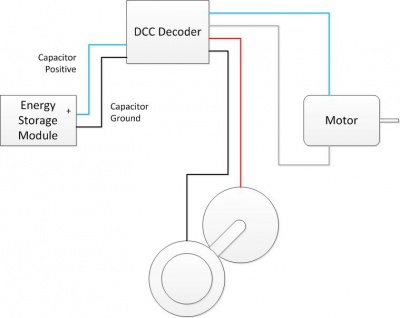
Was this article helpful. It shows the components of the circuit as simplified shapes and the faculty and signal contacts amongst the devices. Decoder wiring colour codes connectors and more. Basic decoder wiring diagram. Nce decoder model. They cover the more modern can style motors as found continue reading dcc decoder.
Dcc decoder wiring diagram hornby dcc decoder wiring diagram repairing hornby 4 pin loco to tender electrical plug posted in electrics non dcc hello is there a wiring diagram schematic print to reference digital mand control dcc brian lambert s dcc page many modern decoders are now using high frequency pwm for the motor drive which eliminates. In fact most brands simply use black for everything so if you want to hard wire a decoder youll have. Follow basic decoder wiring diagram. Higher currents heavier power wiring and overload protection must work. 4 out of 4 found this helpful. The nem 652 or 8 pin dcc plug is one of the standard plugs used for locomotive interfacesthe plug is on the end of a loose wiring harness coming from the decoder and mates with a fixed female socket mounted on the locomotive chassis.
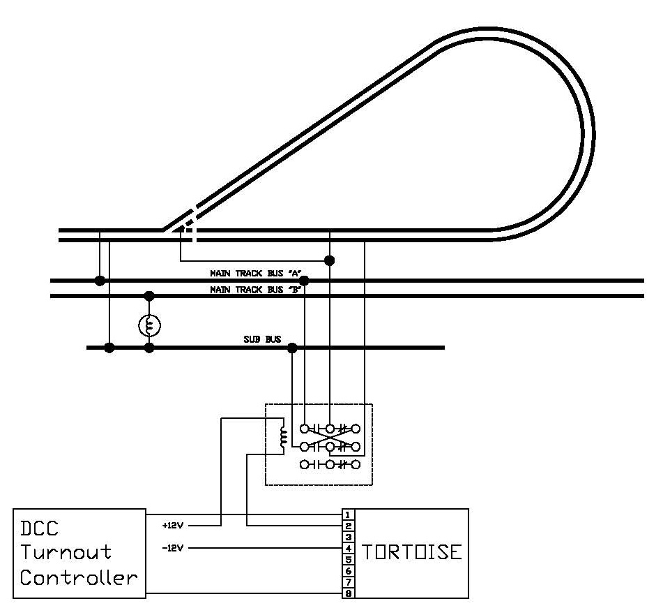
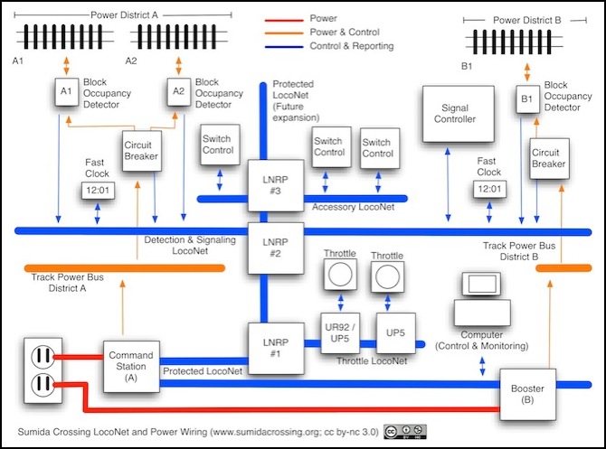
Mobile decoders locomotive wiring and installation kits. Where circuits and wiring are shown these have also been checked or tested however case by case it is possible that exact wire positions may vary with orientation of things like turnout motors. Dcc wiring clinic 25 summary dcc wiring is different from dc blocks and cab control in consideration of wiring methods but many of the same basic rules for electrical gaps etc. Dcc decoder wiring diagram wiring diagram is a simplified within acceptable limits pictorial representation of an electrical circuit.
Gallery of Dcc Decoder Wiring Diagram


.gif)