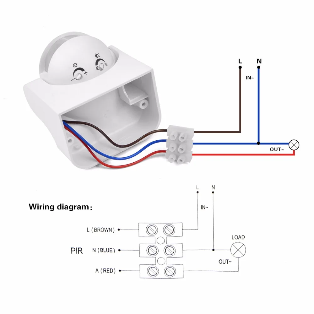
Variety of motion sensor light wiring diagram. A device that reads available light and sends a signal to the control system.

Ce Certification Microwave Motion Sensor Movement Detector
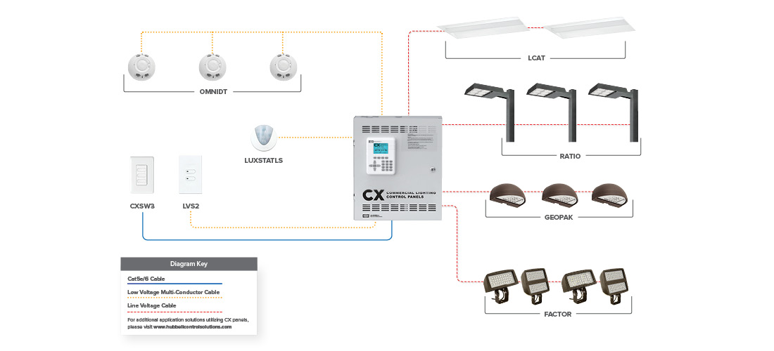
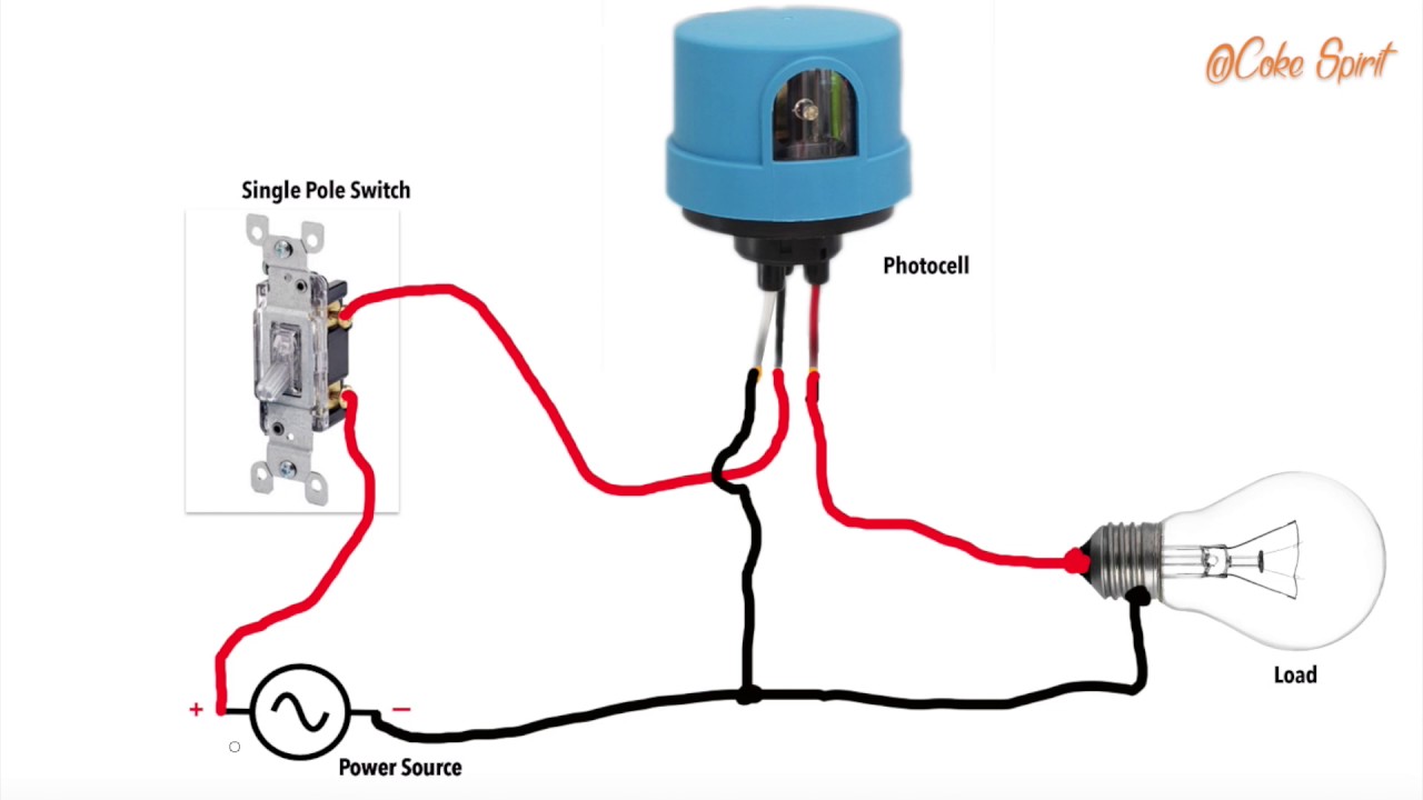
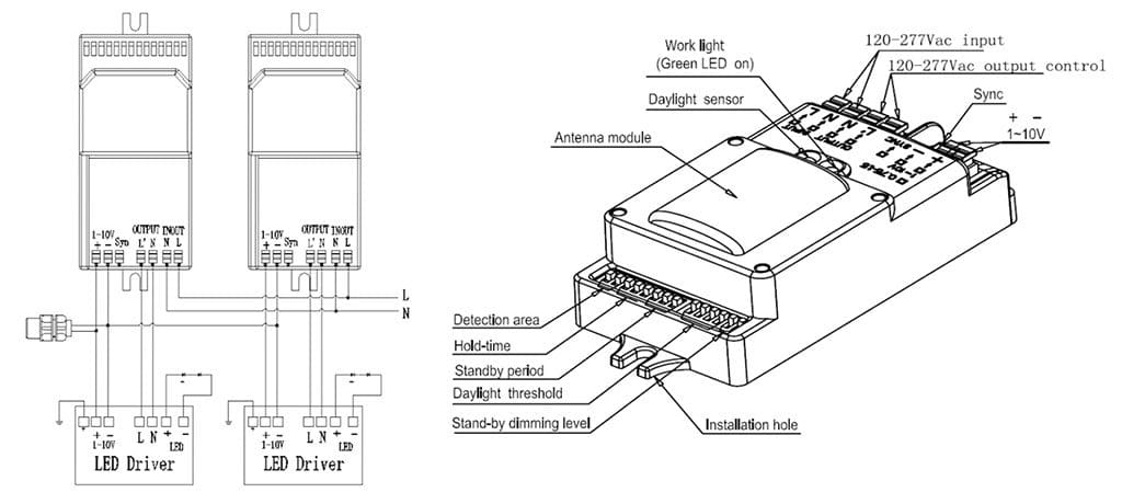
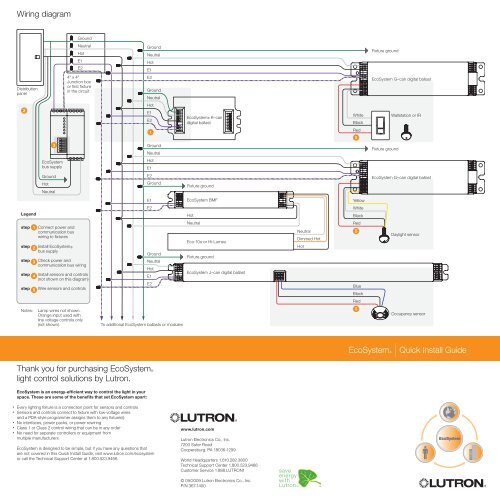
Daylight sensor wiring diagram. A wiring diagram is a simplified conventional pictorial depiction of an electrical circuit. It reveals the elements of the circuit as streamlined shapes and also the power and also signal connections between the tools. Consult wiring diagram a. Within a typical nlight network multiple zones are wired individually to a bridge. Connect sensors black wire to black wire coming from house. Make sure the wire connector is on tight and wrap the connection with electrical tape to help keep the elements from getting inside the wiring.
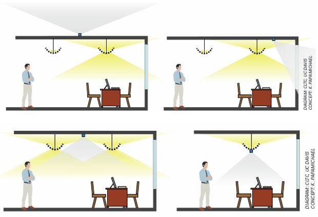
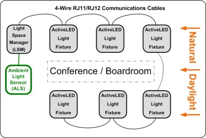
The effective window height h starts 3 ft 1 m up from the floor or at the window sill whichever is higher and ends at the top of the window. A group of fixtures adjusted equally based on daylighting readings daylight sensor. Connect all 3 white wires from house from sensor and from light together. A form of daylighting in which multiple daylight rows are controlled by the same sensor. With light sensors daylight or the lack of it controls the lights operation. Easily monitor control and optimize a lutron control system from any tablet pc or smartphone.
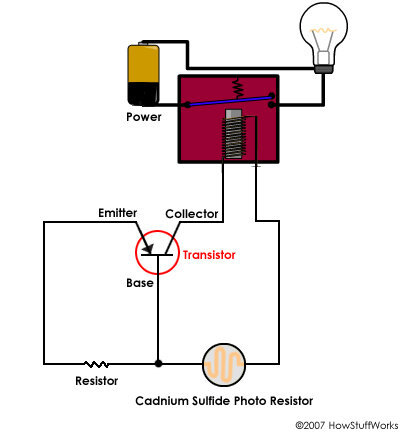
The light sensor circuit is an electronic circuit designed using light sensor ldr darlington pair relay diode and resistors which are connected as shown in the light sensor circuit diagram. Daylight control wiring diagrams blk 120 v orn 277 v cap off pp20 low voltage automatic dimming photocontrols blk 120 v orn 277 v cap off pp20 0 10 vdc ballast dz dual zone option wire to an additional 0 10 vdc ballast. Connect red sensor wire to lights black wire. Connect the white wire from the post with the white wire on the light fixture and the white wire on the light sensor. Grfi systems tm daylight control ackage daylight sensor system 369746a 3 121112 wiring when interfacing to a lutron system the nc. Daylight sensor photo cell photo sensor multiple row daylighting.
Place the daylight sensor so. Nlight control system installation worksheetnlight project installation form. A 230v ac supply is provided to the load in this case the load is represented with a lamp. The arrow on the daylight sensor points toward the area viewed by the sensor. Determine the proper location of the daylight sensor using the adjacent diagram. Specification sumittal page ob ame.
In a room or area that are daisy chained wired together with cat 5 cabling. 40 literature. Contact will turn lights on contact closure close when daylight. Lutrons new facility management tool empowers you to manage your building from anywhere. Black wire is 120 volts so turn off switch or circuit breaker.
Gallery of Daylight Sensor Wiring Diagram