A wiring diagram is a simplified traditional pictorial representation of an electrical circuit. Cutler hammer an16bno wiring diagram cutler hammer motor starter wiring diagram wiring data u2022 rh tani piec co reversing drum switch.
Cutler Hammer Drum Switch Wiring Diagram Wiring Help Needed
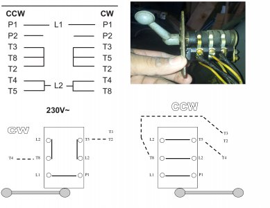
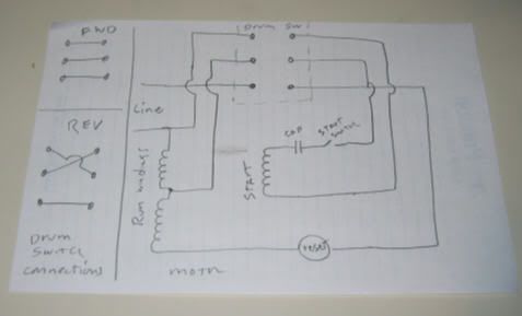
Cutler hammer drum switch wiring diagram. Figure 1 is a typical wiring diagram for a three phase mag. We use cookies to give you the best possible experience on our website. They show the relative location of the components. The diagram is by their wiring diagram. Eaton knows our customers demand a wide range of products and solutions to help them keep power flowing to their homes and businesses. The blue lines are factory installed jumper wires except for the one i added in the middle.
Wiring diagrams sometimes called main or construc tion diagrams show the actual connection points for the wires to the components and terminals of the controller. I am wiring a cutler hammer db1 drum switch to a daytonbison 1lpp4 ac split phase gearmotor but not sure how to do it correctly. By continuing to use this site you consent to the use of cookies on your device as described in our cookie policy unless you have disabled them. Yeah too bad that diagram puts the run windings in series instead of parallel and then says it is for 110v. Whether the application involves residential homes telecommunication facilities hospitals schools or heavy industrial plants our cutler hammer surge protection devices provide protection against the damaging effects of lightning utility switching and. Collection of cutler hammer automatic transfer switch wiring diagram.
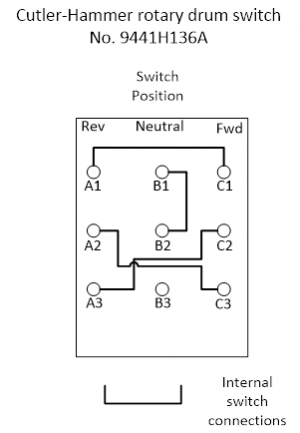
Wiring diagram for cutler hammer drum switch 5441h27a answered by a verified electrician. They can be used as a guide when wiring the controller. It reveals the elements of the circuit as simplified forms as well as the power and also signal links between the tools. Take the red off 3 and connect to 1 take the black off 4 and connect to 2 leave the drum switch in the center position. I googled cutler hammer your drum switch number and single phase and found several what i consider very clear to me wiring diagrams hope this helps. The red lines are the poles that are connected when the switch is activated the left ones to the middle screws when forward is selected the right ones to the middle when reverse is selected.
Each circle in the diagram is a screw. Wiring tutorial for a square d drum switch to a leeson single phase motor for 220230v operation.
Gallery of Cutler Hammer Drum Switch Wiring Diagram