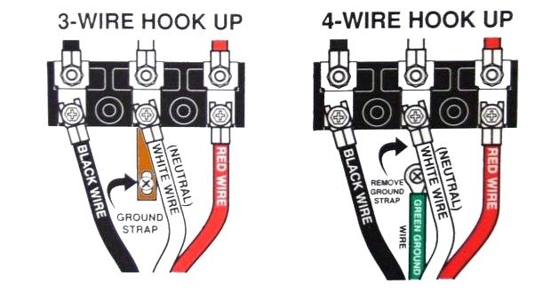
See photo the earth is no problem but i dont know if the green or black is live. Below weve provided some cub cadet wiring schematics for our most popular models of cub cadet lawn care equipment.

Diy Van Electrical Guide Build Your Knowledge Faroutride
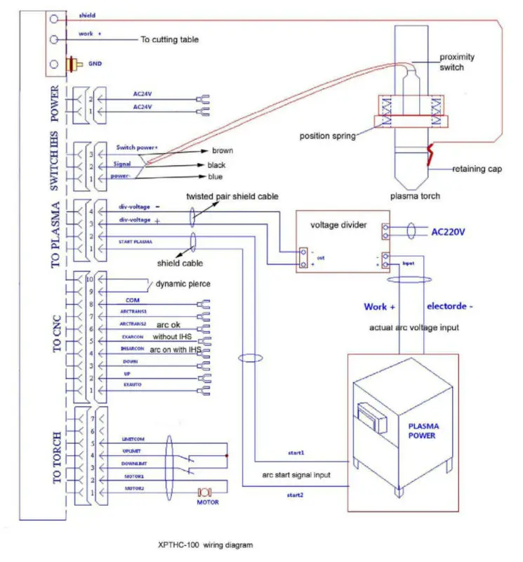
Cut 50 wiring diagram. I am setting up my cut 50 plasma cutter but it does not have a plug fitted and the wiring is strange colours. Everlast welder and plasma cutter wiring video powerarc powertig power i mig. Also the machine says 220v will this run on uk mains at 240v. You can join these wires easily by following the instructions. This could lead to massive sparks and even a fire. Switch wiring diagrams a single switch provides switching from one location only.
Do not mistake one wire for the other. How i tried out the cut 50 plasma cutter duration. The power can come from either the switch box or the fixture box and a set of electrical switch wiring diagrams will explain each of these scenarios to you clearly. Single pole may sound simple but there are different ways to wire a single pole switch. Description catalog cutmaster 50 power supply 208 230vac single phase 60hz with input power cable and plug 3 5230 400vac three phase 50 60hz with input power cable only page 35. Robert nurden timelapse 28966 views.
Step 3 remember voltages for wiring. I would be greatful for any advice before i blow it up. The six gauge cable coming from the panel must have three conductors and a ground. My faded special lp with 50s wiring sounded much closer to my 57 goldtop reissue then my 2008 standard with modern wiring and when i replaced burstbuckers pro with bb 1 2 liked it even more. If youre installing a brand new 50 amp stove outlet the code requires a grounded four pin outlet rated for that current draw. Several voltages need to be memorized for better wiring.
The diagrams were good except as a novice i cannot read how youve hooked up the ground wires. Voltages 208 vac 1 50 amps 70 amp 240 vac 1 43 amps 60 amp and 480 vac 1 25 amps 35 amp go. Thats why i prefer a dedicated volume pot. These schematics are for reference purposes only when you are ready to purchase a specific part please type that number into the search box above. Connect the hot wires to the brass terminals the neutral wire to the chrome terminal and the ground wire to the green one.
Gallery of Cut 50 Wiring Diagram