412 heater circuit the heater circuit is connected to one phase. 11 kv 17 position linear 200 amps dm08.
Transformer Differential Protection Voltage Disturbance
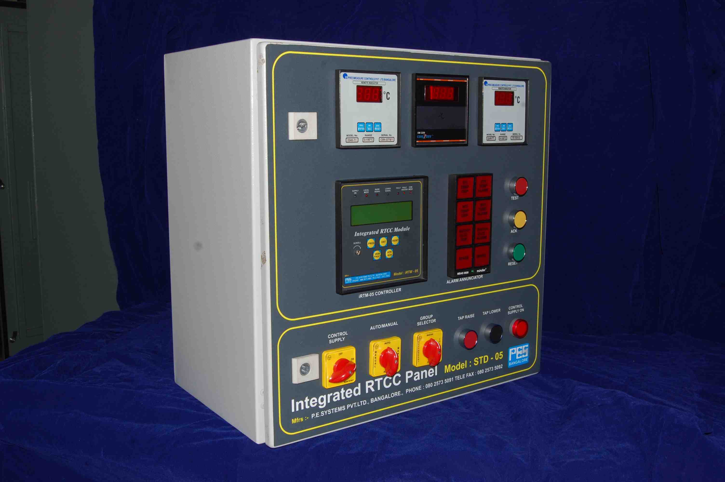
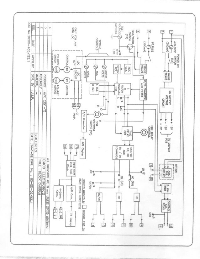
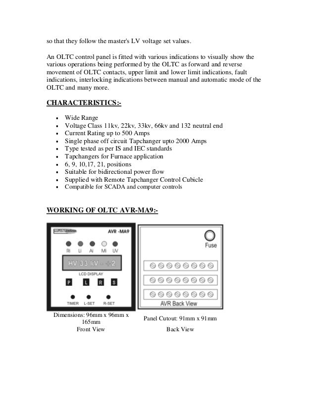
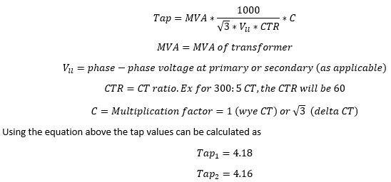
Ctr oltc wiring diagram pdf. T r and ctr wiring shedual diagram pdf file download link httpsdrivegoogle. Table 1 describes the sequence of operations for the tap changer of figure 2 to change from tap 1 to tap 2. This model se avr96 can be fitted into ht panel with minimal wiring scheme. Ready to install and use with any make of oltctransformer. A wiring diagram usually gives recommendation very nearly the relative viewpoint and settlement of devices and terminals on the devices to incite in building or. Ctr oltc wiring diagram wiring diagram is a simplified agreeable pictorial representation of an electrical circuitit shows the components of the circuit as simplified shapes and the capacity and signal links between the devices.
Operation maintenance manual for on load tapchangers type abs ss 1. 33 kv 17 position coarse. Cl08 11 kv 9 position linear 300 amps cm08 11 kv 9 position linear 200 amps cm16. 33 kv 10 position linear 300 amps eo16. Separate rtcc panel not required. 22 kv 9 position linear 300 amps dm16.
See appendix circuit diagram 4 71 529 the motor terminals ryb are connected to the power source via the motor contactor k1k2 the limit switch s6s7 the safety switch s8 and the motor protective relay q1. Complete oltc control and monitoring system. Built in voltage control tap measurement and oltc status indications features. 33 kv 9 position linear 300 amps en16. Changing to any other tap position is done similarly with the selector switch always moving sequentially ie it is impossible to go from tap 1 to. 3 operation maintenance manual for on load tapchangers type a abs 1.
This video is uploaded for technical knowledge only and below is the link to download oltcs wiring schedule. Schematic diagram of oltc. Schematic diagram of oltc. 22 kv 17 position linear 300 amps el08. 33 kv 17 position linear 300 amps en20. The abs ss range of on load tapchanger is housed in a sheet steel tank.
An example of the tap changing sequence is detailed in figure 2 diagrams 1 through 10. The on load tapchanger type a abs is meant for application with dry type transformers both of the cast resin type and of the varnished air insulated type. 33 kv 21 position linear 300 amps eo09.
Gallery of Ctr Oltc Wiring Diagram Pdf