Ii csir cscr csir type मटर potential current relay क wiring आसन स कर. For 1 hp and below the standard configuration of franklin single phase 3 wire motor systems is csir.

Ev 4921 Capacitor Start Motor Wiring Diagrams Together With
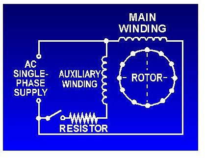
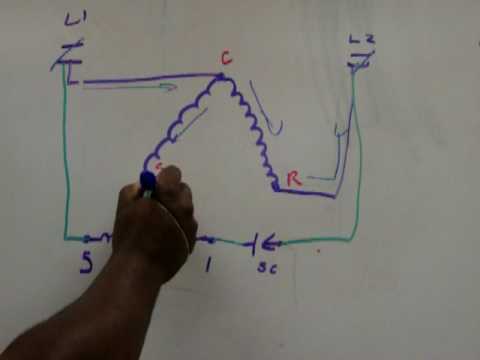
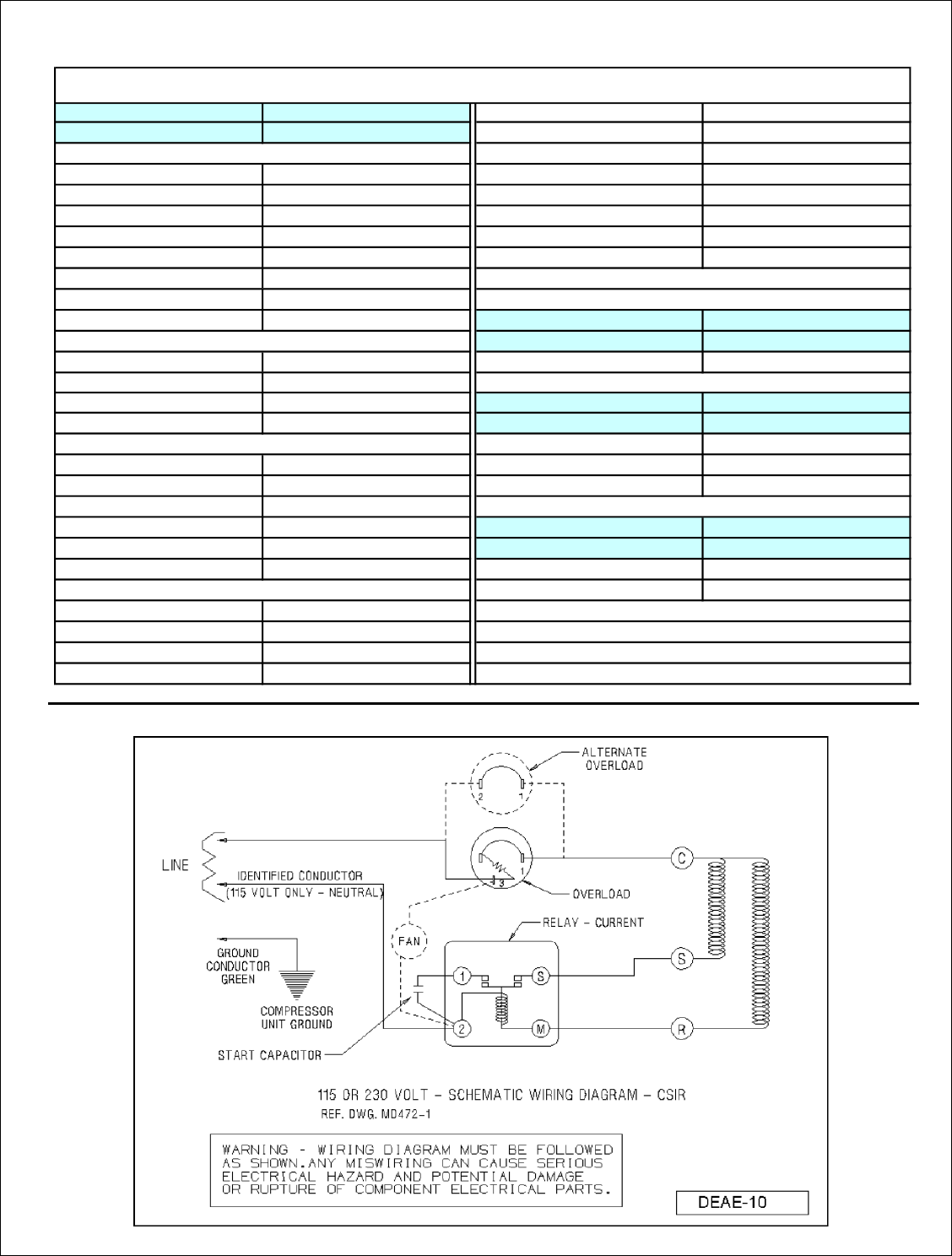
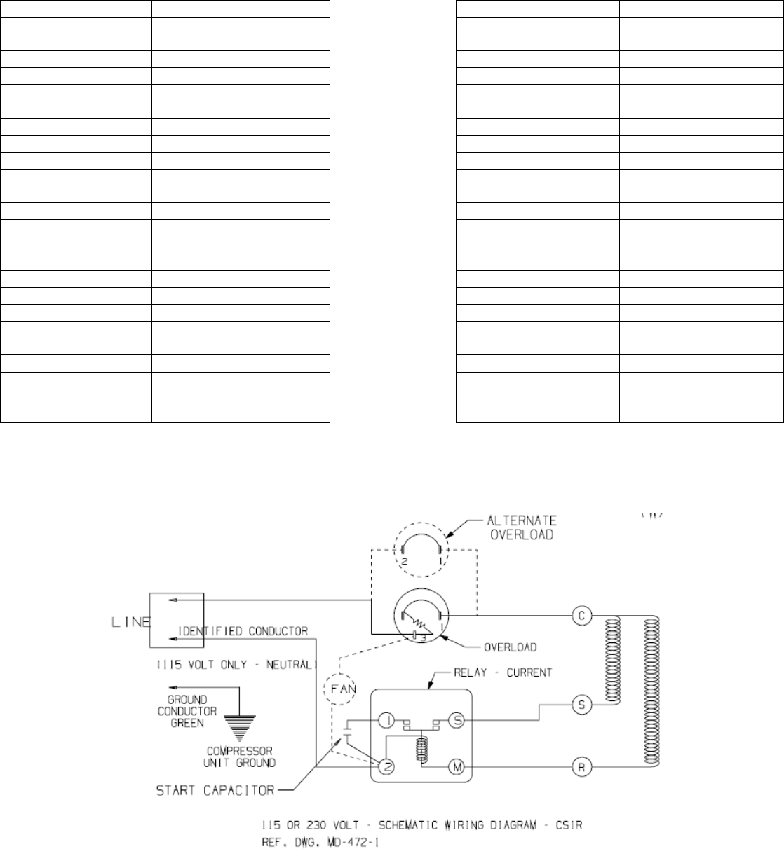
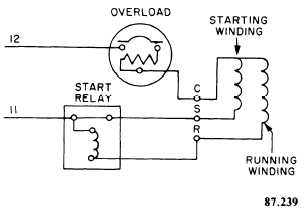
Csir motor wiring diagram. The electrical diagram for the csir motor connected for forward rotation and for reverse rotation is provided in fig. That is there is no run capacitor in the control box. A electrical diagram of a capacitor start induction run csir motor connected for forward. Inst maint wiringqxd 5032008 1002 am page 6. 1 overview of single phase connection for grundfos 3 wire control boxes fig. Dayton capacitor start motor wiring diagram wiring diagram pdf.
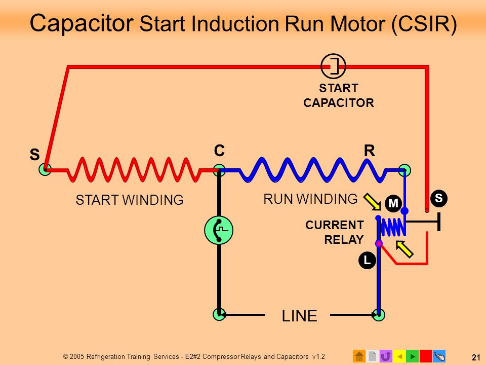
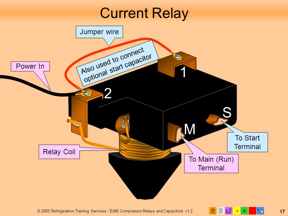
The start capacitor is usually rated for over 100 microfarads up to 1000 uf. Csir wiring diagram download read online. Line 1 line 2 ground control relay current external. These diagrams are current at the time of publication check the wiring diagram supplied with the motor. Start capacitor and inrush facts myths part 2 hvac school pdf. 2 connection of 037 075 kw sa csir models tm06 5330 4615 tm06 5331 4615 control brw blk gry box fused switch brown yellow and green black grey use dotted line.
Cscr wiring diagram if youve heard the terms csir and cscr and wondered what they mean youre not alone. Single phase motor wiring diagram wiring diagram single phase motor wiring diagram in for ac the jpg. Long running applications such as fountains and aerators are the most common examples. Csir cscr csir type motor potential current relay wiring easily. Download csir wiring diagram free files. Refer to the motor manufacturers data on the motor for wiring diagrams on standard frame ex e ex d etc.
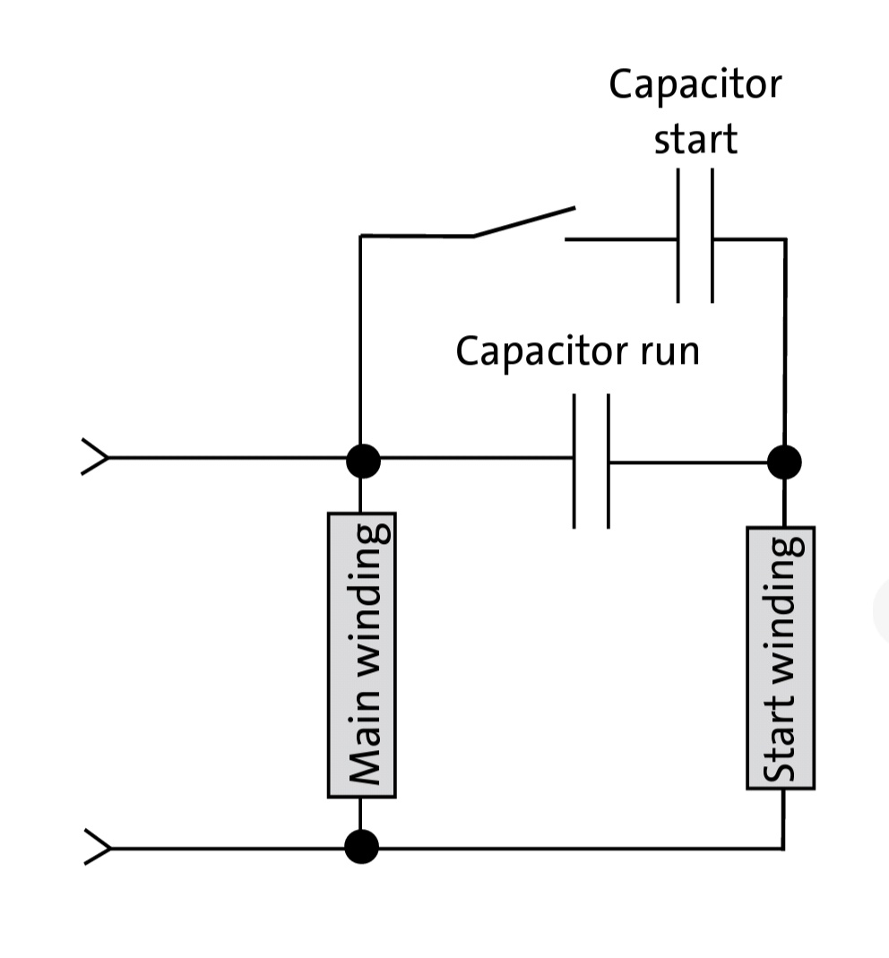
A wiring diagram of a single speed psc motor is shown in figure the capacitor start capacitor run cscr motor has the highest starting torque. 4 t m thermal protector identified conductor 115 volt only neutral line 1 line 2 ground. Ii hindi s u. Start winding main winding. This is a common question and the answer may have a significant effect on how your motor runs depending on its size. Rsir motor diagram with wired in ptc relay.
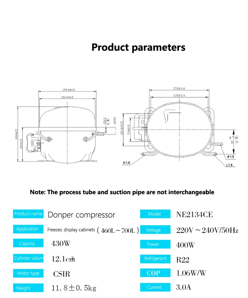
However in some cases there may be a need to convert these installations to a cscr configuration. 34 thermal protector control. Always use wiring diagram supplied on motor nameplate. Hencesyntron cscrc v control it is important to follow the wiring diagram provided with the control when making electrical connections. 59e6465 hermetic compressor wiring diagram embraco wiring pdf. English gb 6 332 wiring diagrams fig.
Ptc relay compressor unit ground alt.
Gallery of Csir Motor Wiring Diagram