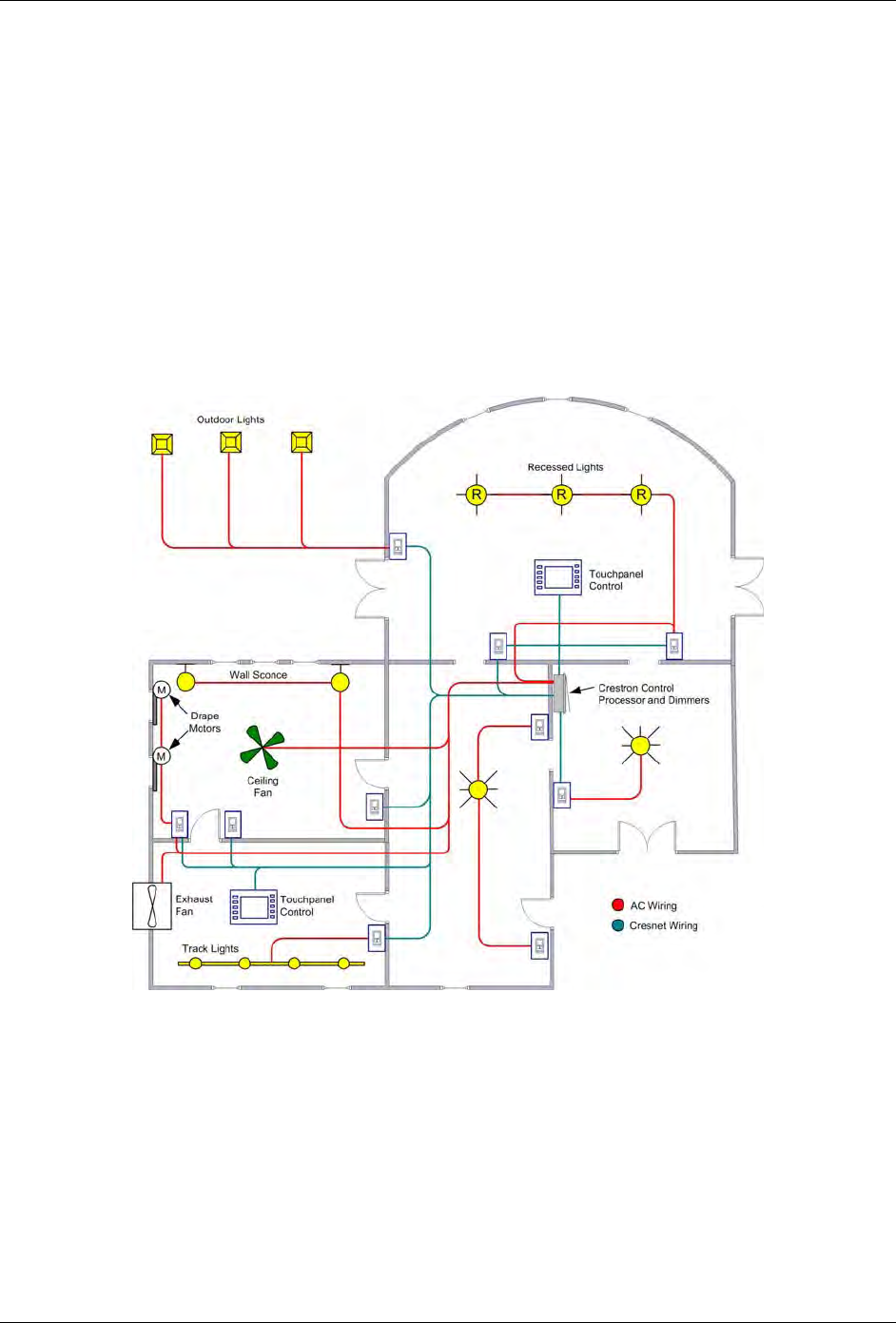
Control system crestron lighting example lighting system this example is based on the following typical wiring plan. Crestron electronics dimmer 0 10 v lighting control electronic crestron residential lighting design guide crestron residential lighting design guide lighting and automation crestron residential lighting design guide.
Crestron Wiring Diagrams F7 Wiring Diagram
Crestron lighting control wiring diagram. To ensure optimum performance over the full range of the installation topology use crestron certified wire. Crestron lighting control wiring diagram sample. 32 lighting control system design design guide doc. Crestron integrated lighting system author. Dimmers and switches. A wiring diagram is a streamlined standard photographic representation of an electrical circuit.
Switch control point in a multi switch single circuit application. Sensors 24 1 4 g connects to photocells. Crestron simplifies design installation and startup of commercial lighting control with zūm lighting control. Use 18 12 awg wiring. A wiring diagram is a streamlined standard photographic depiction of an electric circuit. Crestron simplifies design installation and startup of commercial lighting control with the right products and systems designed to work for the individual needs of each space in a building and integrate easily together for enterprise wide monitoring management and control.
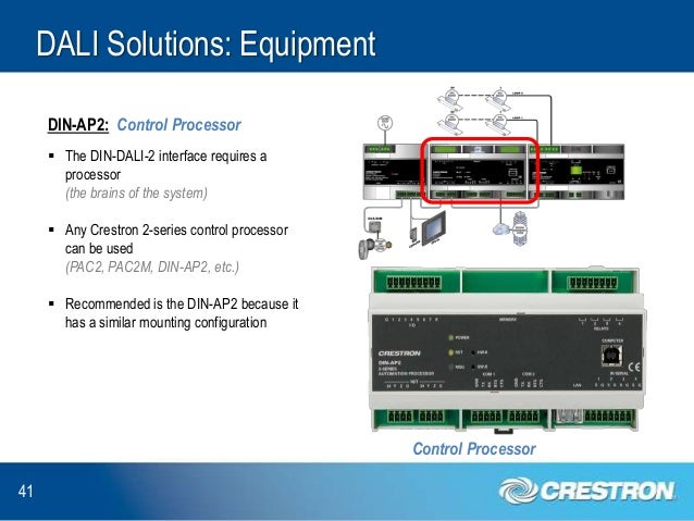
Whats people lookup in this blog. Crestron residential lighting design guide crestron residential lighting design guide crestron residential lighting design guide design guide 230 v lighting. A wiring diagram normally offers information regarding the relative position and plan of gadgets as well as terminals on the gadgets to assist in building or servicing the gadget. 24 supplies power to the devices andcrestron green light lighting design integrationdm 50 switch wiring diagram wiring library. Assortment of crestron lighting control wiring diagram. Page 37 control system enter the information into d3 pro and the software can generate the following load schedule reports.
Assortment of crestron lighting control wiring diagram. Integrated lighting system load wiring diagram section a control wiring section b use crestron certified wire such as cresnet np or cresnet p. Failure to do so may incur additional charges if. Crestron lighting control wiring diagram. Wiring diagram sensors 24 1 4 g connects to occupancy sensors. Use 18 12 awg wiring.
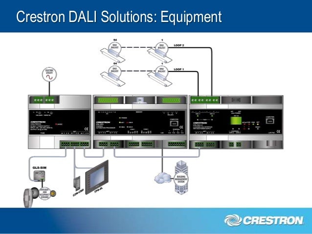
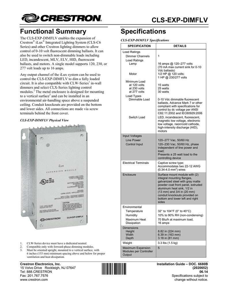
Wiring diagram of clw device to cresnet. It shows the parts of the circuit as simplified shapes and also the power as well as signal connections between the tools. Light emitting diode led with software adjustable. It shows the elements of the circuit as streamlined forms as well as the power and signal links in between the devices. Ck 3957 dali wiring diagrams free diagram schematic. Crestron integrated lighting system.
Gallery of Crestron Lighting Control Wiring Diagram