The following diagram shows a c2n uni8io in a lighting and av system application. Cresnet low voltage wiring andor rf control can be used.

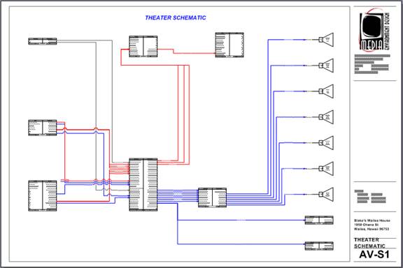
Yacht Lighting
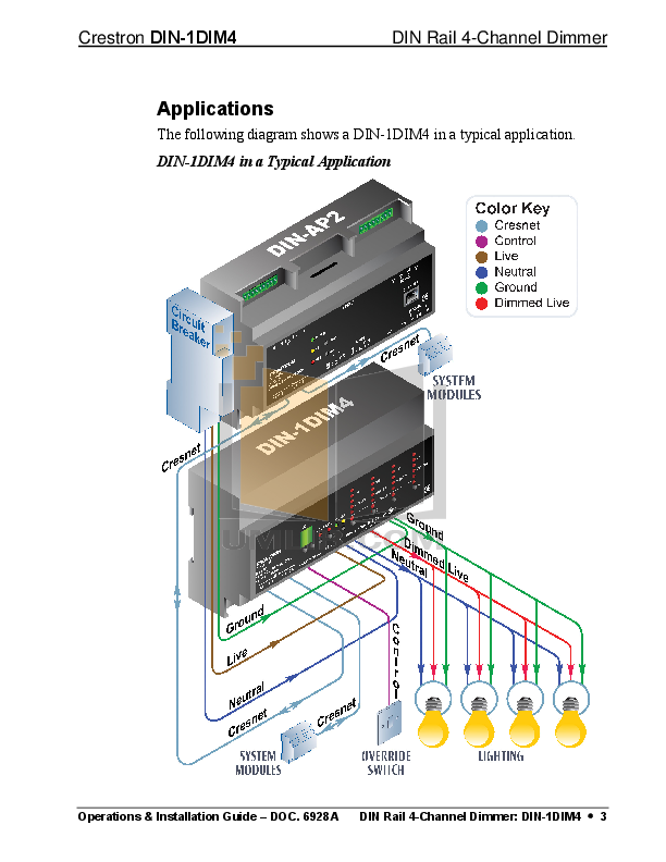
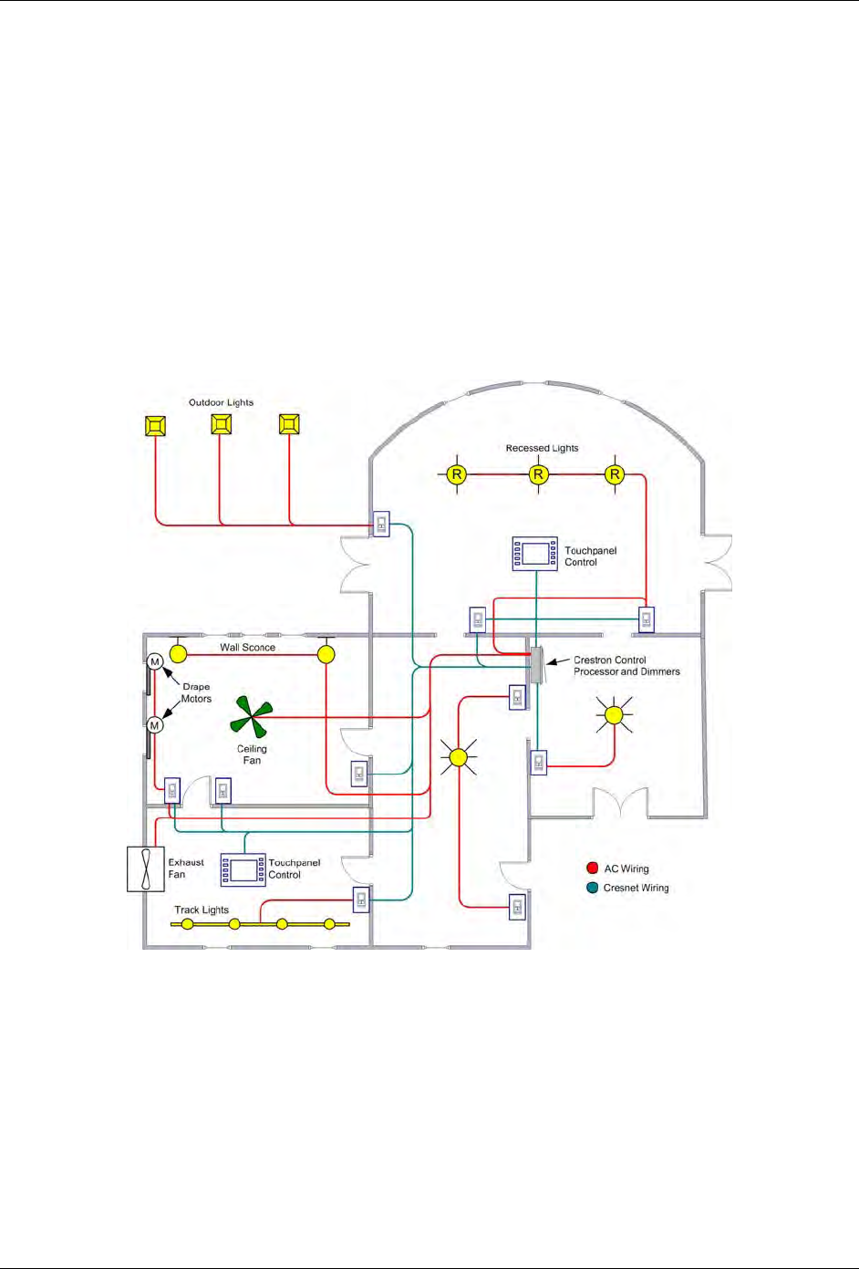
Cresnet wiring diagram. Cresnet network wiring is 2 twisted pairs 1 pair 18awg for 24 gnd 1 pair 22awg for data yz with shield. Shorting non current limited supplies maythermostats crestron chv tstat and chv thstat quick installation reference 1. System integrators normally need to evaluate scenarios and pricing in order to arrive at a solution. The external ac power pack does not supply power to this port. Shield should be connected at power supply end only. Finally the black wire is the ground side of the power pair to complete the cresnet connections and wiring.
The two net 4 pin network connectors are used to connect the 4 wire cresnet devices to the cen cn. Power can be provided via the net connection and the. Cresnet cable is a low voltage rated cable and should. Cresnet hp network wiring is 2 twisted pairs 1 pair 12awg for 24 gnd 1 pair 22awg for data yz with shield. How to create a crestron control system overview by using a topology diagram. Cresnet 8 high voltage 8 c2n uni8io cresnet 8 low voltage 100ma 8 cen ci3 3 tcpip up to 48 low voltage 1a up to 48 there are more possibilities than the examples mentioned above.
The white wire is the y communication of the rs 485 bus which is the positive side of communication pair. This flexible 4 wire bus normally supports approximately 20 cresnet devices without requiring a hub. The blue wire is the z communication of the rs 485 bus and this is the negative side of the bus pair. Often they require assistance from. The 24vdc at this port is available only if supplied via cresnet wiring connected to the 4 wire net ports. Din rail cresnet distribution hub crestron din hub three segment cresnet hub cresnet is the communications backbone for crestron lighting modules wall box dimmers shade controllers thermostats keypads touchpanels and many other devices.
The complete diagram is available on line at.
Gallery of Cresnet Wiring Diagram