Computer power supply wiring diagram computer power supply connector diagram computer power supply pinout diagram computer power supply wiring diagram every electrical structure consists of various distinct pieces. That increases your voltage drop and power dissipation in the cable.

Diy Pc Bench Power Supply Schematic Diy Pc Computer Power
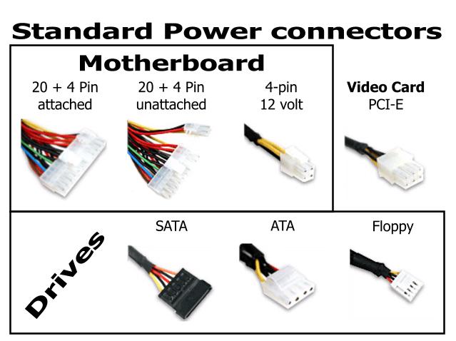
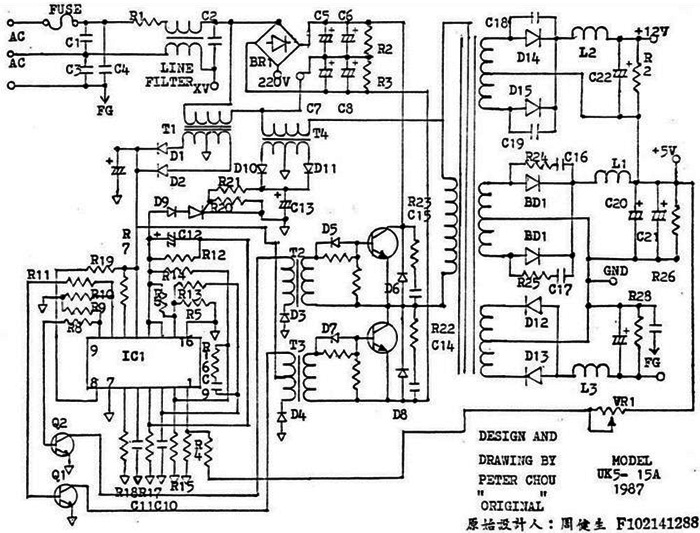
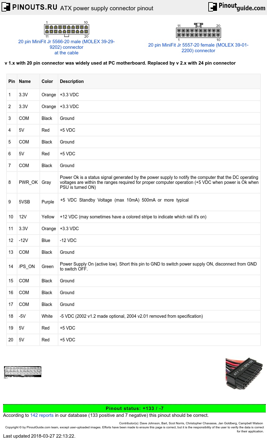
Computer psu wiring diagram. The most common type of todays psu is the switch mode power supply smps. However they all use the same basic concepts. In addition to the old at standard atx 20 has one extra voltage line available 33v a connector chain lined to the single 20 pin and a power on wire that allows software to turn off the psu. Each part ought to be set and linked to other parts in specific manner. In order for your psu to work when not connected to the mother board the green wire must be connected to any ground wire. Redign sitch yellowconstant 12v blackground very important.
Yellow12v red5v orange33v blackground wiring from stereo. To provide the additional wattage the old part has been replaced by a new 24 pin p1. Also note the dual wire crimped onto pin 13 33v at the motherboard end of the connection which goes to pin 13 and also pin 20 on the psu end of the connection. This page explains the principals of operation of a switching mode power supply and reviews its main parts and functions. Variety of dell laptop power supply wiring diagram. Atx specification includes not only power supply unit but also interface to case and motherboard.
A computer power supply converts the ac power from the wall outlet into smaller dc voltages that power the various components of the computer. If you wish to add a switch to the psu so you dont have to unplug it all the time carefully take apart. Connect the red wire from the usb cable to the red wire from the power supply. This has an additional wire looks like awg20 or 22 crimped onto the same pin as the main wire. These diagrams reflect the front view. Accordingly different atx style psu may use different number of power wires.
There is a wide variety of smps topologies and their practical implementations used by psu manufacturers. A wiring diagram is a streamlined traditional pictorial depiction of an electrical circuit. Some current high end video cards can suck up more than 10 amps at 12 volts with most of it coming through the pci express connector so it pays to be careful. Simplified circuit diagram of a typical psu diagram of a typical xt and at voltage regulator circuit internals of a psu with passive pfc left and active pfc right the desktop computer power supply changes alternating current from a wall socket of mains electricity to low voltage direct current to operate the processor and peripheral devices. This is a sense wire which is used to fine tune voltages at load. The colors in this chart represent recommended wire colors in the psu cables.
See the pinout diagram to the right. The colors are shown here. It reveals the elements of the circuit as streamlined forms as well as the power and also signal connections in between the gadgets. It regulates the voltages by rapidly connecting and disconnecting the load circuit switched mode power supply. Plugging them both into the same psu cable forces your video card to draw its 12 volt power through one 18 gauge wire.
Gallery of Computer Psu Wiring Diagram