The first one is the original class a loop and second one back feeds on the separate pair of wires to make the second class b loopmost of the devices on the original class a loop will be. This module accommodates both 2 and 4 wire smoke detectors no.
Fire Alarm Class A Wiring Diagram Geboy 2012 Rmnddesign Nl
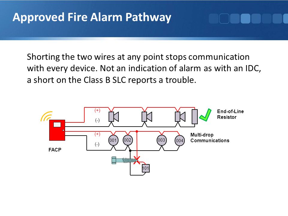
Class b fire alarm wiring diagram. A wiring diagram is a streamlined traditional pictorial representation of an electrical circuit. Required for each facility. But because the wiring is supervised by the fire alarm panel however as soon as the connection is broken the panel indicates there is trouble. The broken wire can be fixed right away. Not only do they indicate there is. A wiring diagram is a simplified standard photographic depiction of an electrical circuit.
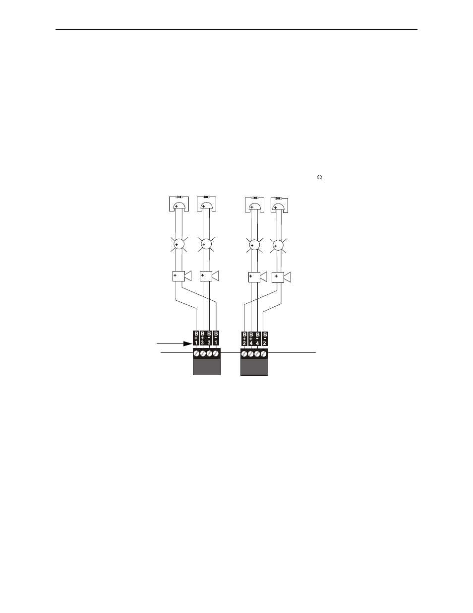
When describing a class the nfpa is concerned with is reliability fixability and survivability. December 22 2018 by larry a. Class aclass b zone installation initiating zone modules each initiating zone module provides up to 2 class a style d 4 class b style b or 1 class a and 2 class b zones of protection. If the nfpa addressed this kind of wiring path though the class of wiring would be class dont. System wiring explains the differences between slc class a and class b circuit wiring use of. It shows exactly how the electrical cords are adjoined and could additionally reveal where.
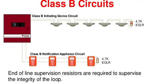
Wellborn assortment of class b fire alarm wiring diagram. A pathway classification describes more than that. If a connection or wire is broken class b wiring systems stop working properly. This pair along with the eol makes up a fire alarm loop. It shows the components of the circuit as streamlined shapes and also the power as well as signal links in between the devices. Basically when the fire alarm panel detects an open wire in the class a loop it automatically switches to using two separate un supervised class b loops.
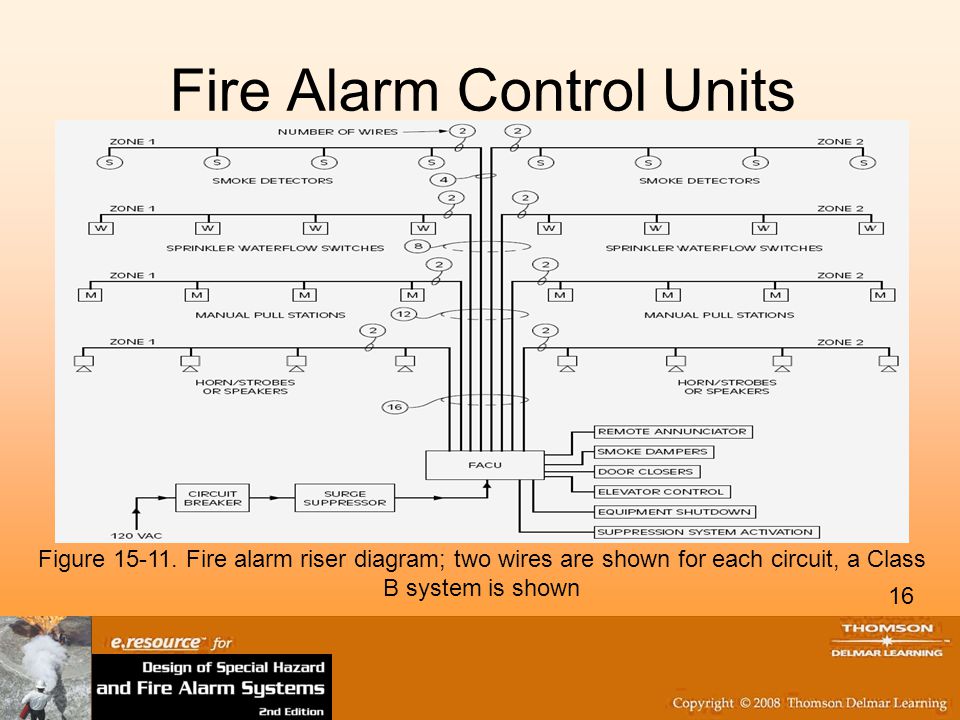
Different types of fire alarm system such as conventional addressable intelligent and smart wireless designs are used for the same purpose ie. A wiring diagram is a basic aesthetic depiction of the physical links and physical design of an electric system or circuit. Class a wiring systems go a step further. It reveals the components of the circuit as simplified forms and the power and signal links in between the devices. Fire alarm systems are wired in industrial factories offices public buildings and nowadays even in homes. Class b wiring is supervised it is continually checked for continuity by the fire alarm control panel using a small electrical current.
Types of fire alarm signals and differences between conventional addressable and analogaddressable fire alarm systems are also presented. Reliability the nfpa wants to make sure the fire alarm system continues to work in the long run. In case of emergency the sounders will operate to warn the people around to evocative via general or emergency exit. The current as it leaves the panel goes out one of a pair of wires goes through a current limiting resistor called an end of line resistor eol and returns on the other wire. Class b fire alarm wiring diagram download 2 wire smoke detector wiring diagram collection exactly what is a wiring diagram. By headcontrolsystem collection of class b fire alarm wiring diagram.
Alarm initiating de vices and no.
Gallery of Class B Fire Alarm Wiring Diagram