These cars can have either a 4g or a 6g series alternator installed. Just got a gx engine has the 10 amp charging system.
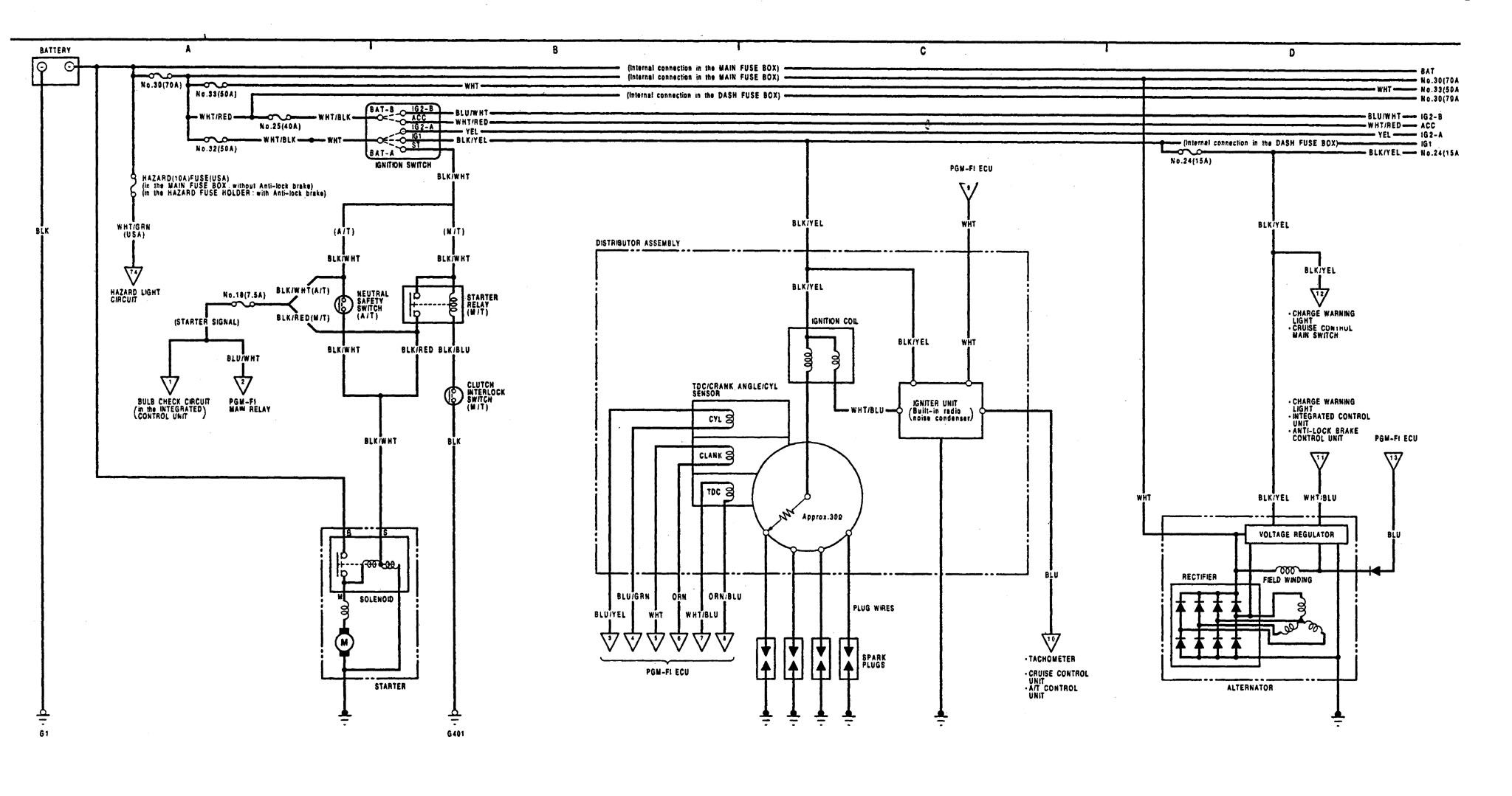
Acura Integra 1991 1992 Wiring Diagrams Charging
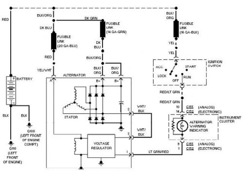
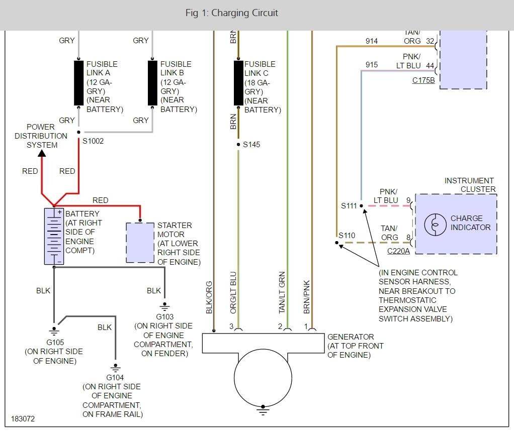
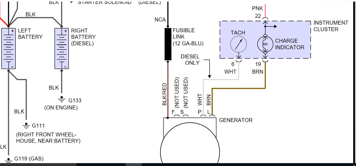
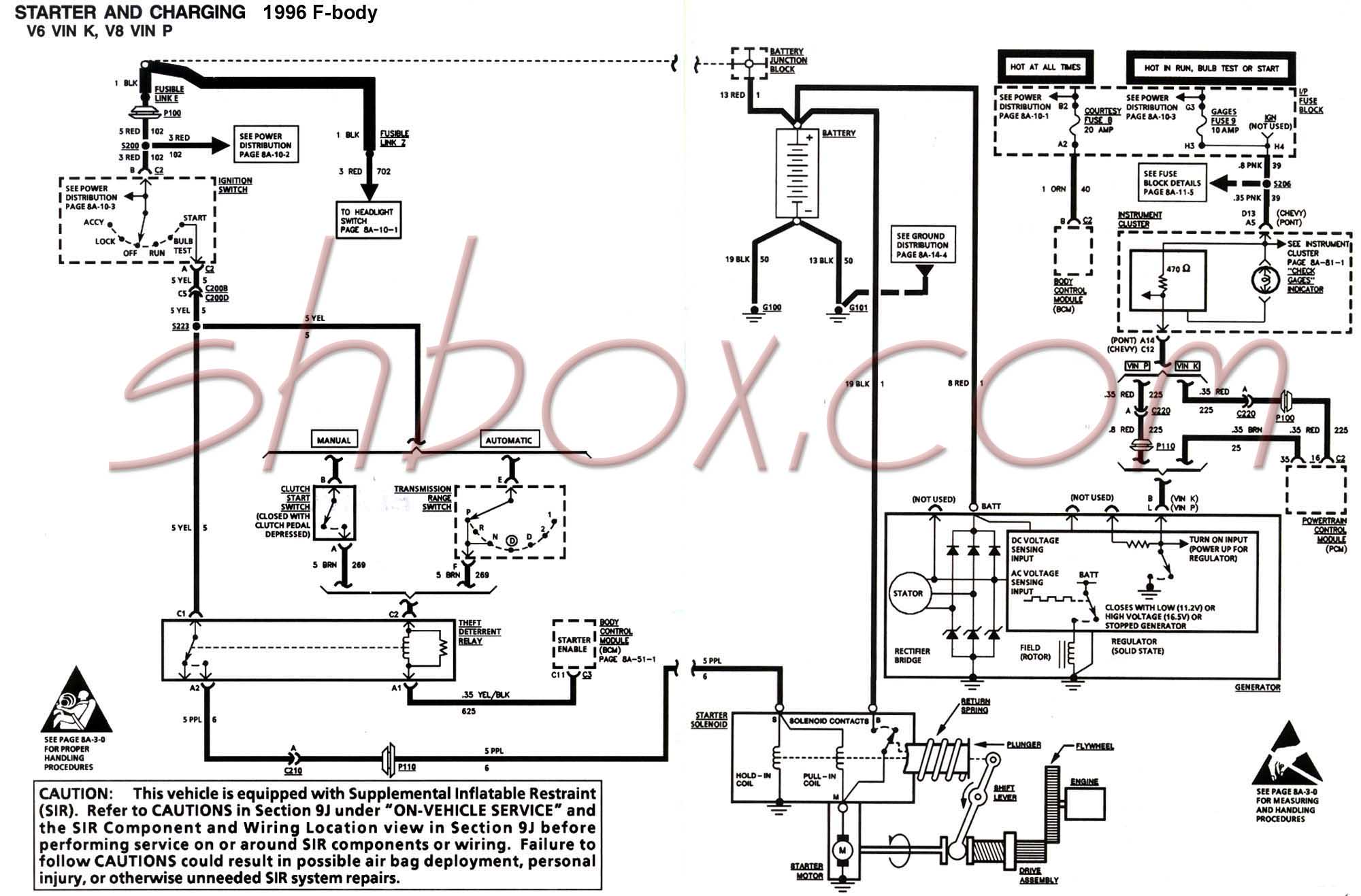
Charging system wiring diagram. Here is a wiring diagram of the charging system used in the 1998 2002 crownvics. Learn the current flow electrical characteristics and peculiarities of modern charging systems. Use a shunt if the system you are testing. Established in 1990 purkeys has always focused on providing products that charge and protect batteriesand other cool stuffon big trucks including inventing the first ever liftgate charging system. Many people have spoken to me over the years about how confusing and strange their charging system wiring is on their cucv vehicles. Aturn off the ignition switch and connect a dmm set to measure dc amps as shown.
The following tests are performed when the charging system is operating normally but the battery discharges either while the engine is running or while the engine is off. The gnd brush is grounded with the brush mounting screw. 800 x 600 px source. And coming from fly wheel. They are as follows. Charging page 2 of 3 honda engine charging system.
800 x 600 px source. The control circuitry is the same for both alternators but the electrical connector that connects to the regulator is different between the 4g and 6g alternators. Wiring diagram includes many comprehensive illustrations that display the connection of varied items. There are 2 brushes in the alternator each one has a field terminal one is labeled fld the other is labeled gnd. It includes directions and diagrams for various types of wiring strategies along with other things like lights home windows etc. Coil inspection chart in the appropriate shop.
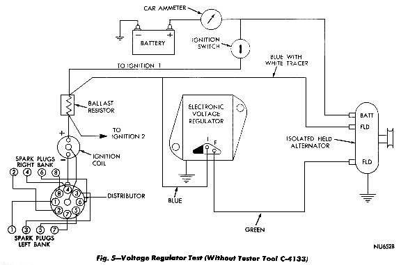
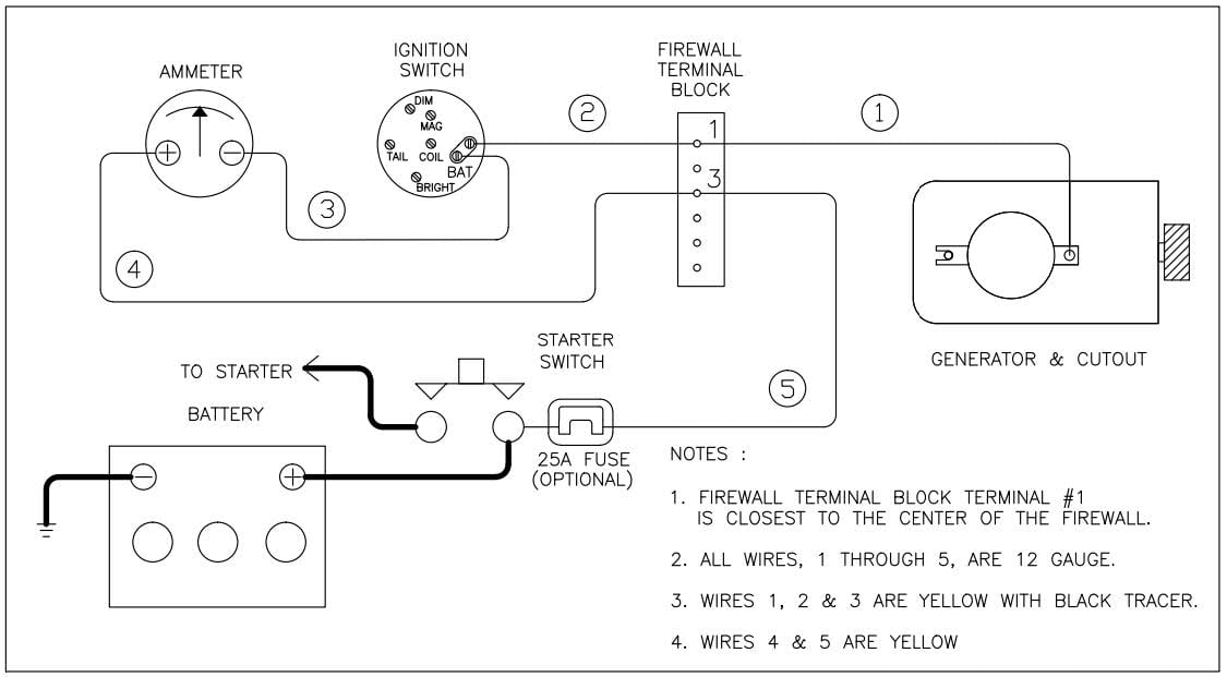
Diagram 1 shows the basics of the early alternator voltage regulator vr design. I hope that this series of photos and information will help shed some light on the subject. Keeping heavy duty vehicles safely on the road with happy drivers happy technicians and happy fleet managers is purkeys goal. Were is the rectifier located on the wiring diagram is on page parts catalog to determine the engines charging system rated capacity. Mopar charging system pre 1970 diagram 1 shows the basics of the early alternator voltage regulator design. Mopar charging systems.
Inspiring charging system wiring diagram case contemporary size. This first photo illustrates the wires that should terminate at your gen2. Basic wiring diagram for all garden tractors using a stator and briggs and stratton charging system wiring diagram. There are 2 brushes in the alternator each one has a field terminal one is labeled fld the other is labeled gnd. Part of our wiring diagram analysis series of videos shown here on this channel.
Gallery of Charging System Wiring Diagram