This started by the scoot just shutting off when i was riding it. My colors and number of wires dont match up.

50cc 2 Stroke Moped Army
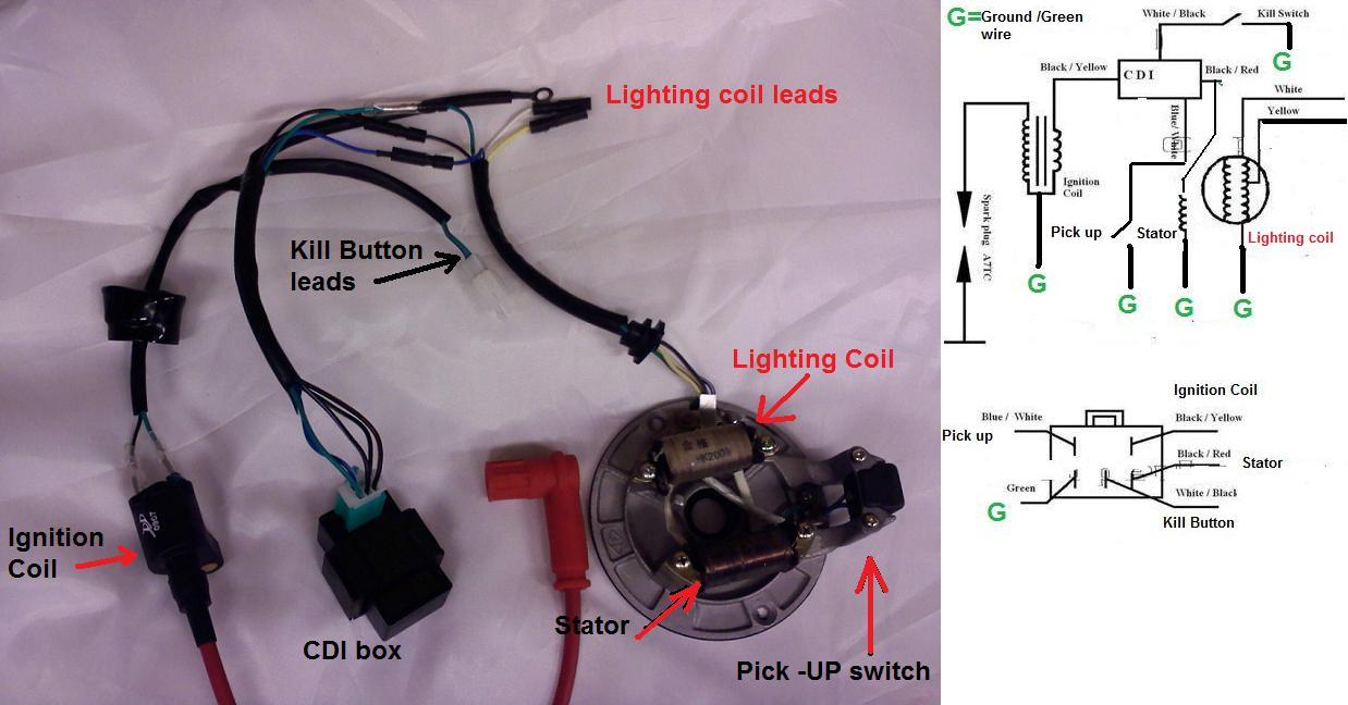
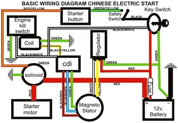
Cdi stator wiring diagram. I have a znen pacifica 150 zn150t 18 and im having trouble figuring out the color hook ups for the wires on the cdi and stator. The stator is the plate holding all of the electrical coils of wire which is used to power on the ignition coil bikes lights and battery charging circuits. Green wire at cdi to ground key off ground o ohms key on 300 ohms ive had the scoot for three years bought it new. I do have 2 vdc on the bluwt pulse wire from stator to blkwt at cdi 4 plug when cranked. It reveals the parts of the circuit as simplified shapes as well as the power and also signal connections between the devices. Honda cx500 cdi stator wiring diagrams for ignitech and rae sa before using this site please read the site disclaimer.
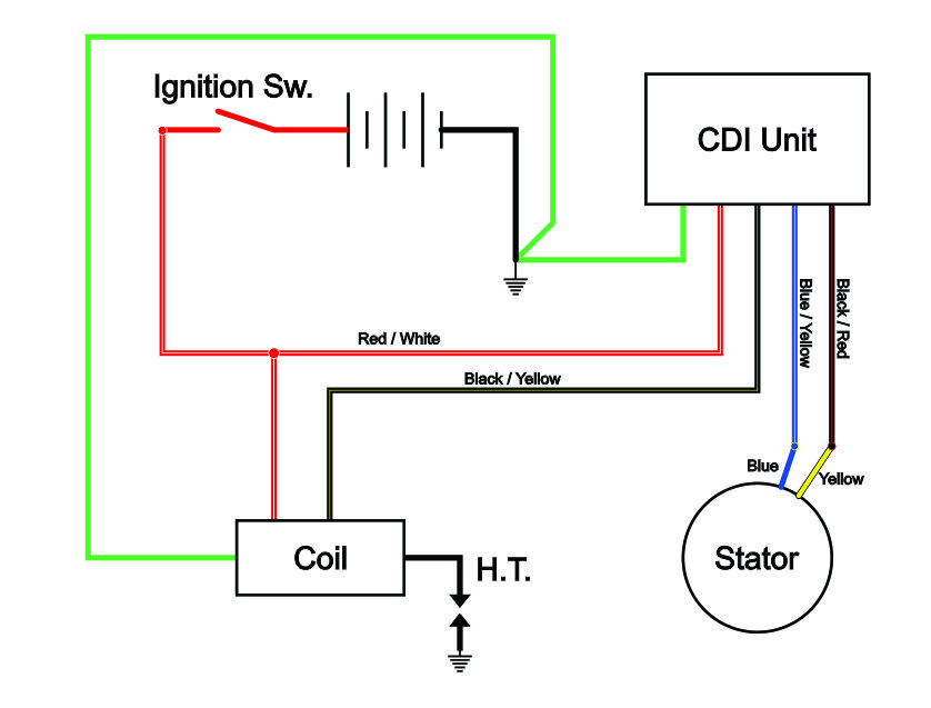
Ebay amazon which helps support the site as i will earn a commission when visitors make a qualifying purchase. Charging coil the charging coil is one coil in the stator which is used to produce 6 volts to charge the capacitor c1. It should be approximately 80 on oem stators and 28 32 on cdis. Check resistance from red to redwhite. The voltage regulator is not connected disconnected. Troubleshooting the stator no fire at all.
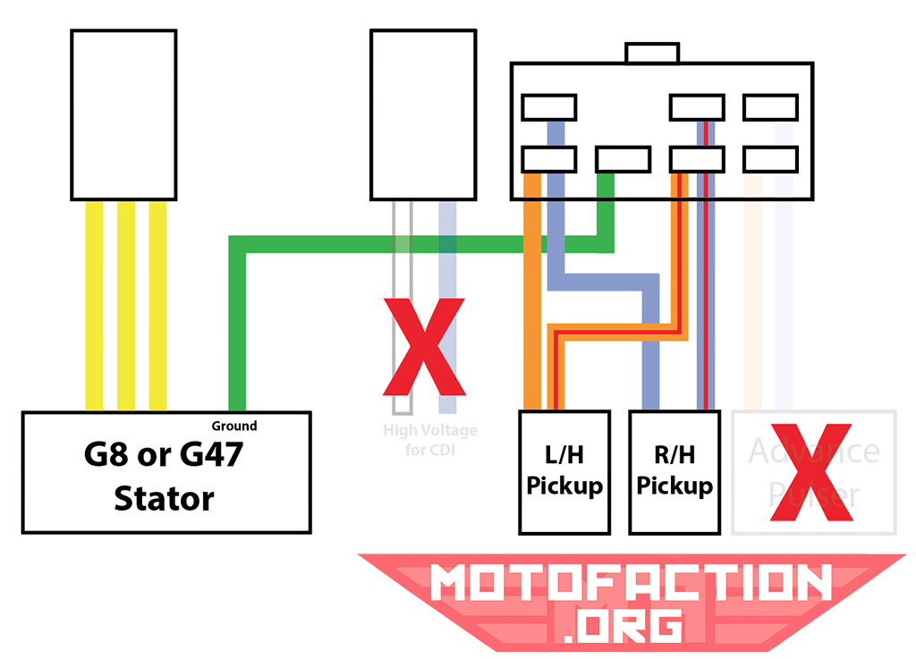
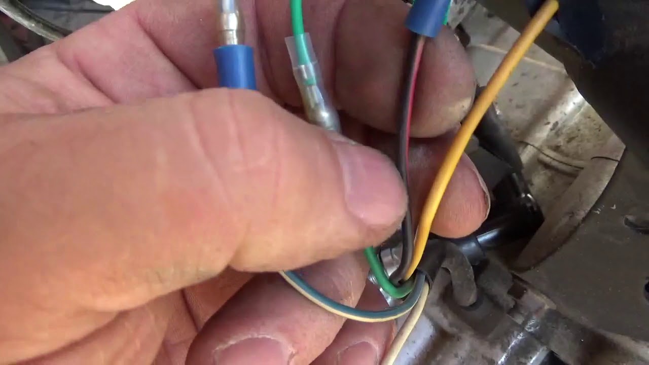
A wiring diagram is a streamlined traditional photographic depiction of an electric circuit. Here is the chinese engine code chart with the example of the jog 2stroke gy6 engines are on the fron bottom left had side near the centerstand pivot. Hello all it has been a while since i came on the forum. Collection of mercury outboard wiring diagram. Check resistance from the blue to the bluewhite stator wire. Wires coming off are 3 yellow 1 green and 1 blue and white.
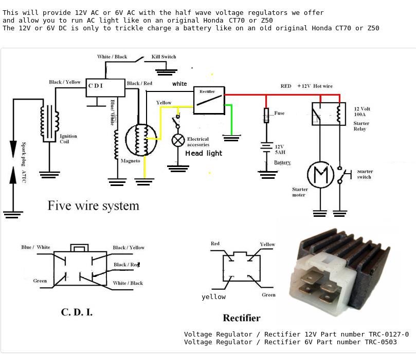
This is the 6 coil stator common on most 50cc scooter but also can be found on a here is a wiring diagram of the typical 5 wire cdi system on a lot of scooters. Oem will read approximately 3500 ohms cdi stators will read from 500 700 ohms. Cdi circuit using an scr a few resistors and diodes referring to the above capacitor discharge ignition circuit diagram we see a simple configuration consisting of a few diodes resistors a scr and a single high voltage capacitor. The stator is an 11 pole. Also please note that any links provided may be part of an affiliate programme viz. May 26 2020 cdi quality better than oem jun 26 2017 cdi electronics supports the 2017 national skillsusa competition jun 28 2016 cdi electronics announces new lower pricing for ficht emm repairs.
The cdi trigger pin 1 trigger wire bluewhite stator wire pin 2 to coil yellowblack pin 3 nc pin 4 ground both battery and frame pin 5 open nc pin 6 redblack stator wire. Im confused as usual. The input to the cdi unit is derived from two sources of the alternator. Voltage at the redblack stator wire not connected to cdi is 110 v ac.
Gallery of Cdi Stator Wiring Diagram