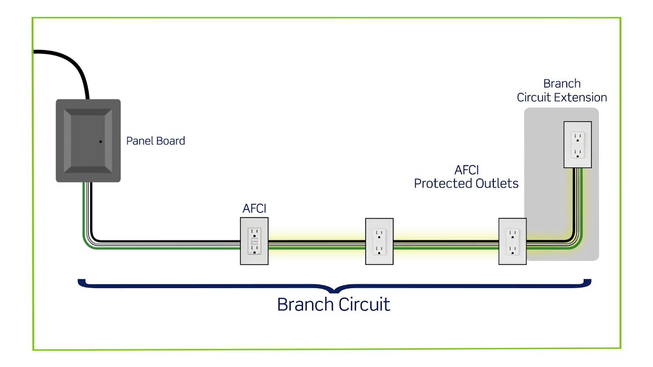
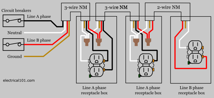
The 142 awg cable for this circuit includes 2 conductors and 1 ground wire. Branch circuits for 120 volt circuits are usually 15 amp or 20 amp circuits although occasionally they will be larger than that.
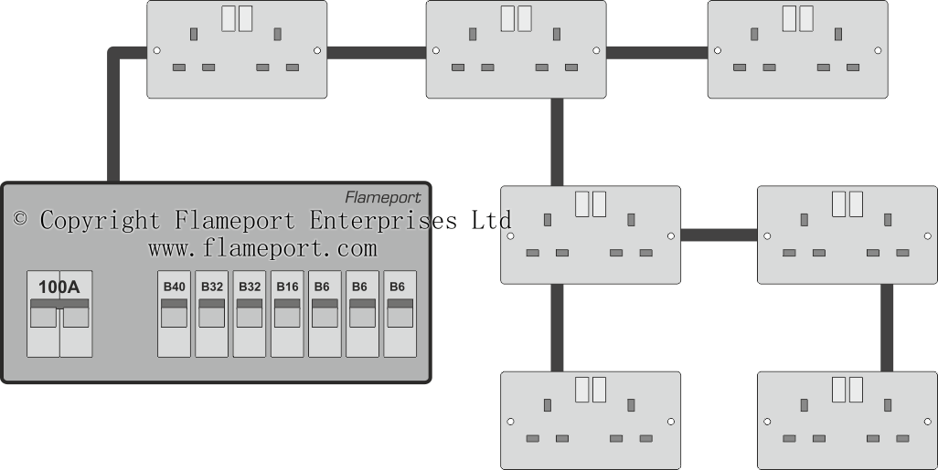
Radial Circuit With Branches
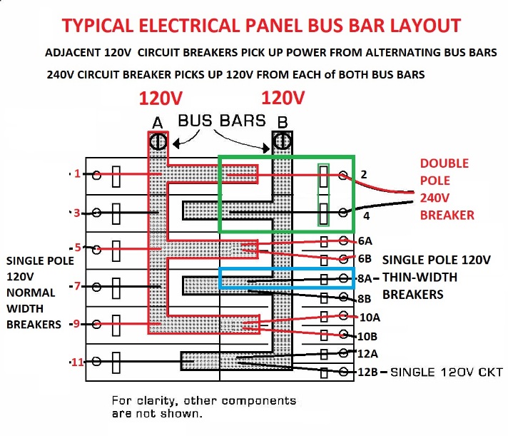
Branch circuit wiring diagram. For 249 volt circuits the amperage is more often 30 40 or 50 amps. Multi wire branch circuit wiring diagrams. A multiwire branch circuit in the electrical code is defined as a branch circuit that consists of two or more ungrounded conductors two or more hot wires that have a voltage between them they are not on the same electrical phase and so are connected to different buses in the electrical panel and a grounded conductor the neutral wire. Why are multiwire branch circuits used. The white wire is the neutral providing return current for both of the a and b phase 120v. The amperage of each branch circuit can be read by the printing on the lever of each circuit breaker.
Wiring for two 20 amp 120 volt circuit breaker. 3dwelling unit branch circuits can supply only loads within or associated with the dwelling unit. Multiwire branch circuits can offer fewer conductors reduce the raceway size and reduce voltage. See example diagrams below. This photo is an example of a multiwire branch circuit incorrect wiring diagram. The bare copper wire is the ground.
This wiring diagram illustrates installing a 15 amp circuit breaker for a 120 volt branch circuit. A 15 amp circuit is usually used for wall receptacle outlets and room light fixtures. The red wire is usually the b phase 120v. This photo is an example of a multiwire branch circuit preferred wiring diagram. Multiwire branch circuits that supply devices or equipment on the same yoke must also be provided with a means to disconnect simultaneously all ungrounded conductors that supply those devices or equipment at the point where the branch circuit originates 2104b fig. Receptacle ground connection diagram shown separately.
Gallery of Branch Circuit Wiring Diagram