Keep these instructions with the brake control for future reference. Secure the brake controller into the mounting bracket.

Hopkins Impulse Brake Controller Trailer Wiring Diagram Best
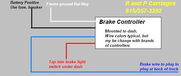
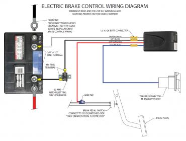
Brake controller wiring diagram. If you would like to give some information about your vehicle i could make a more specific recommendation on how to wire it and let you know if any other parts are needed. Electric brake controller wiring diagram. Read and follow all instructions carefully before wiring brake control. Connect the ground wire to the white wire on controller will attach to the ground on the harness. Return to the duplex cable under the hood where the brake wire now white needs to be separated from the 12 volt hot lead black. Using a 1012 butt connector connect this wire to the brake controls blue wire.
The red wire on the controller will attach to the lead from the brake light switch. Break away systems may be added to the service brake circuit. The brake control must be installed with a 12 volt negative ground. Installing a brake controller involves disconnecting the vehicle battery mounting the brake controller onto dash and plugging the unit in with a vehicle specific wiring harness. Auxiliary connection is optional it may be connected to any 12v to 24v constant power source or left unconnected. Connect the brake controls red wire to the cold side.
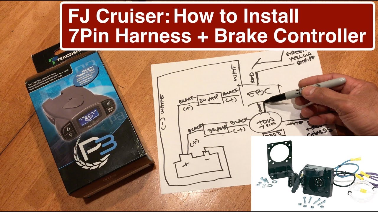
The wiring diagram to the right is a basic brake controller hook up. Read and follow all instructions carefully before wiring brake control. Wiring instructions for electronic brake controls pn 4399 rev k generic wiring diagram read this first. Important facts to remember 1. There will be four wires each separately labeled on the harness. Elecbrakes is designed to operate 1 to 2 braked axles.
If your vehicle is not equipped with a plug and play harness you can also splice in wiring for connecting a brake controller. It shows the elements of the circuit as simplified forms as well as the power and also signal connections between the devices. Generic wiring diagram read this first. Keep these instructions with the brake control for future reference. The brake control must be installed with a 12 volt negative ground system. Some newer vehicles provide their own brake control jumper harness which makes the install a plug and play affair.
All brake controllers wire pretty much the same with a white ground wire a black power wire a red brake switch wire and a blue brake feed wire that goes to the trailer brakes. A wiring diagram is a simplified traditional photographic depiction of an electrical circuit. Run a 12 gauge or larger blue wire from the tow vehicles trailer plug brake terminal to the brake control. Attach the white wire from the battery area to the brake controls white wire. Connect the brake controller harness to the electronic brake controller using barrel crimp connectors. October 4 2018 by larry a.
Important facts to remember 1. The four wires on the brake controller will be connected shortly. The wiring harness shown is typical of any electric brake control installation. In this guide we cover step by step how to install a brake controller. Wiring the 7 way trailer connector and brake controller. Wellborn collection of prodigy brake controller wiring diagram.
Gallery of Brake Controller Wiring Diagram