Bnc connector wiring diagram diagram of cctv installations bnc connection cctv rg59 cable bnc connector wiring diagram wiring diagram is a simplified welcome pictorial representation of an electrical circuit. Initially designed as a miniature version of the type c connector bnc is a type of connector used with coaxial cables such as rg58 and rg59 rf applications that require a quick connector suitable for uhf and constant impedance over a wide spectrum.
Triaxial Cable Wikipedia
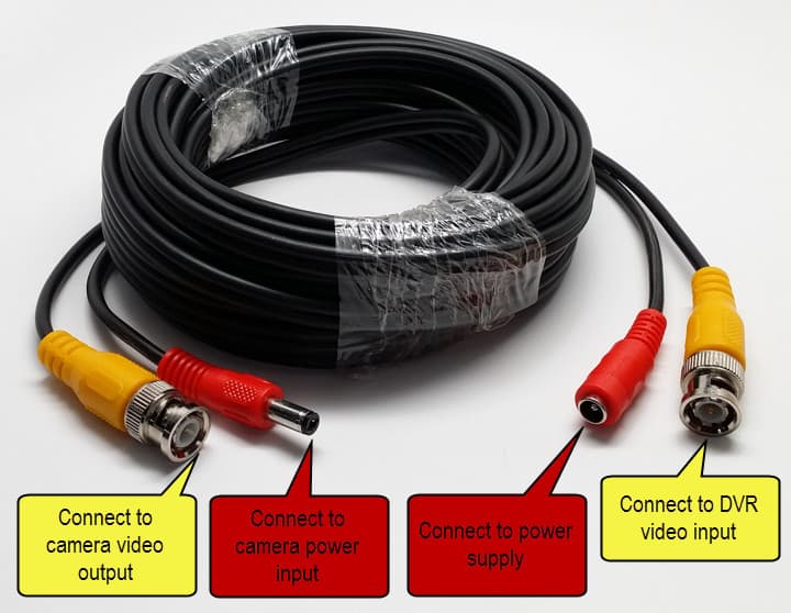
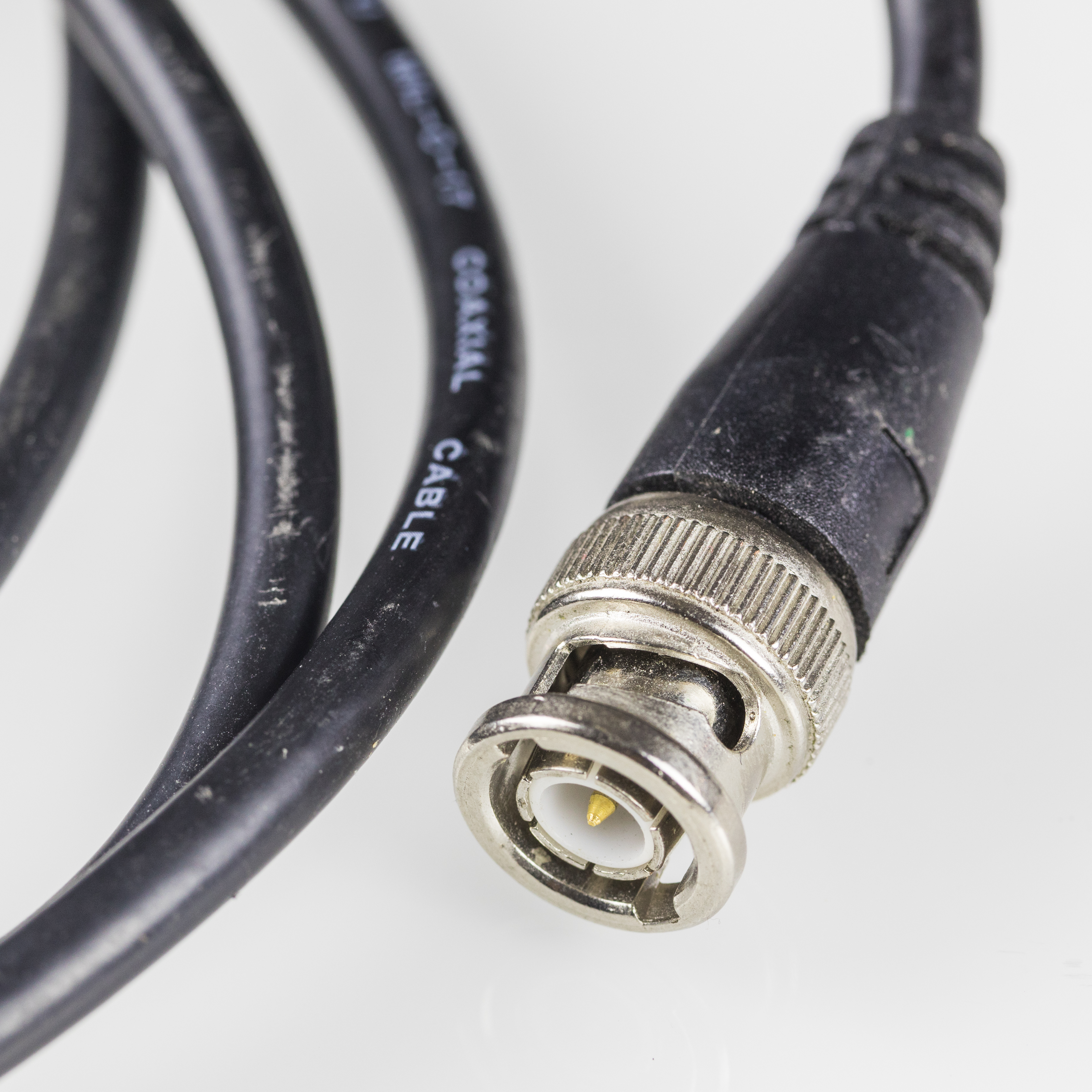
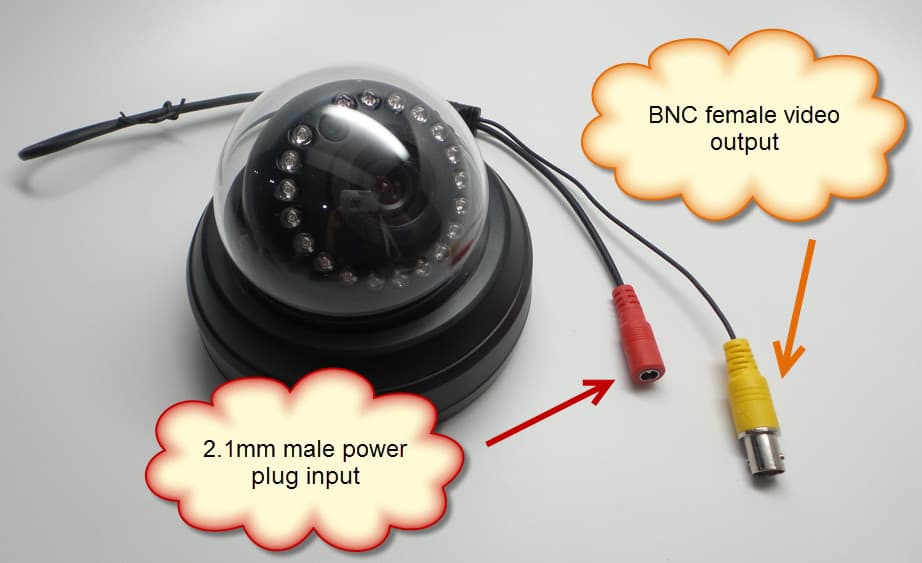
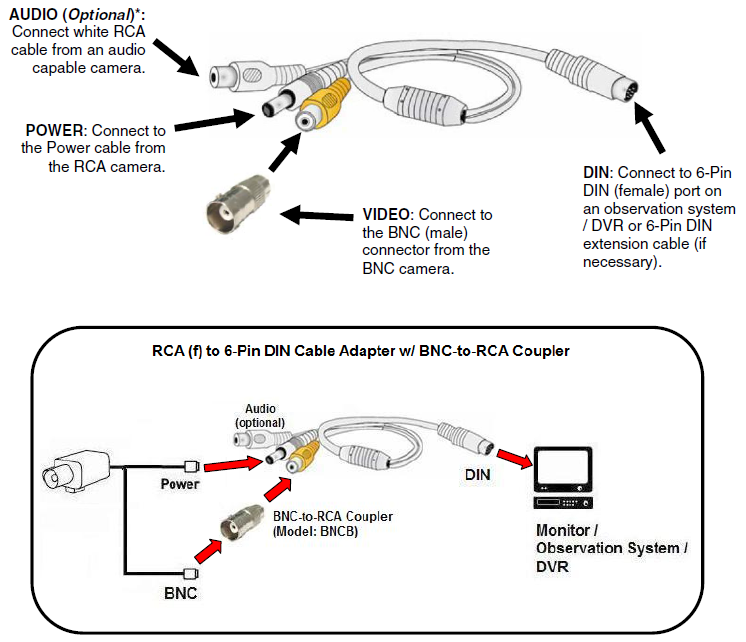
Bnc connector wiring diagram. Here is the schematic diagram of bnc connector parts and components. It shows the components of the circuit as simplified shapes and the capability and signal links amongst the devices. The red one is for positive cable with dc ability of 5 volts. For power some cameras have terminals to accept bare wire. Bnc connectors are crimped onto the rg59 coaxial cable to be plugged into the cameras video port. In accordance with how to splice bnc to usb wiring diagram there are just four wires used from the cable.
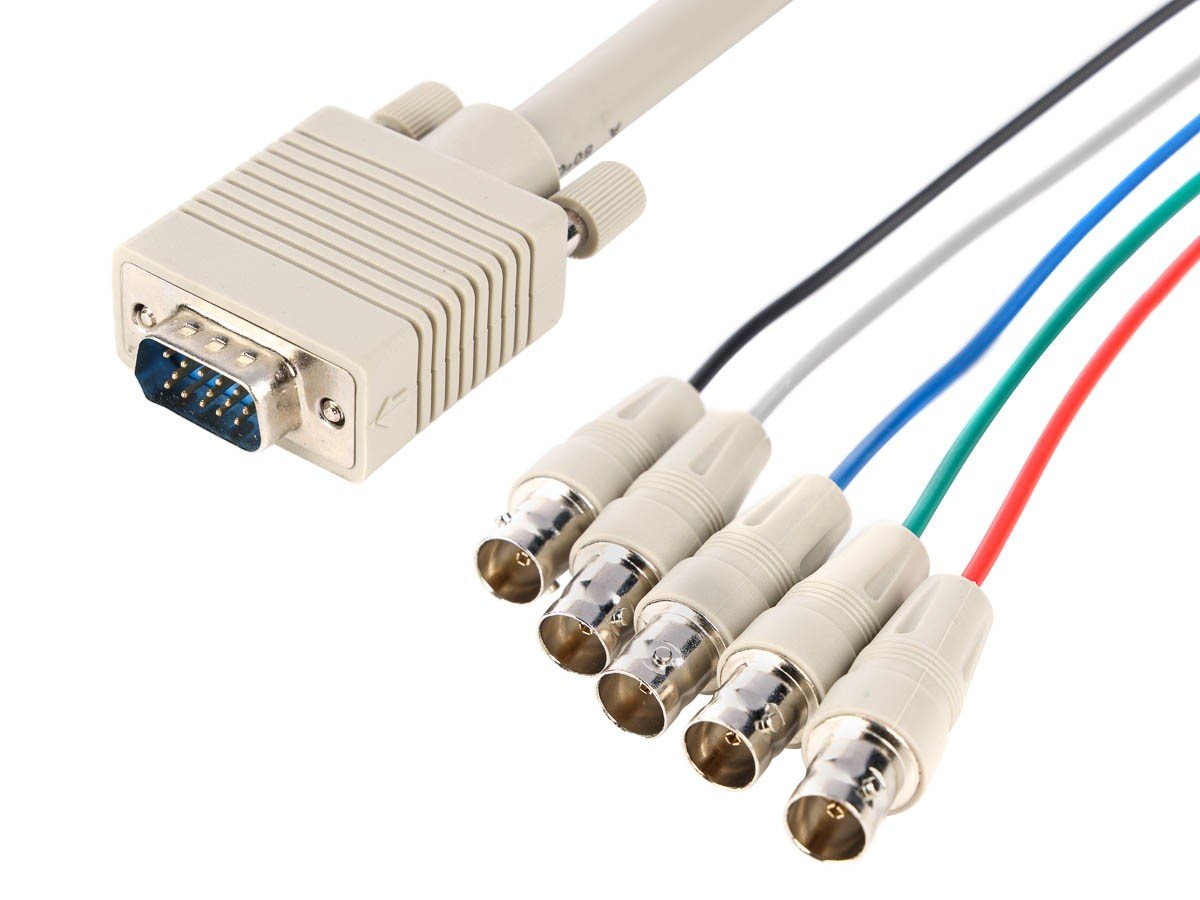
Typically it utilizes black green red and white wire colours. The bnc cables are used for video signal transmission while the rs 485 cables are used to control the camera movement and rotation by connecting it to the joystick ptz controller or dvr system. Others require a connector be attached to the wires to plug into the camera. This tutorial describes using a three part bnc connectordeveloped in the late 1940s as a miniature version of the type c connector bnc stands for bayonet neill concelman and is named after amphenol engineer carl concelmanthe bnc product line is a miniature quick connectdisconnect rf connector. 30w1 00200 picture the red wire is positive and the black wire is negative. The following wiring diagram shows that how to connect an analog ptz camera to the dvr and joystick ptz controller.
Rg59 coaxial cable power terminal. Black wire serves as floor just like in every other apparatus.
Gallery of Bnc Connector Wiring Diagram