Turn signal flasher info and wiring mechanical 2 prong old style explained duration. Collection of 3 pin led flasher relay wiring diagram.
Turn Signals Integrated Into Tail Lights The Honda Side By
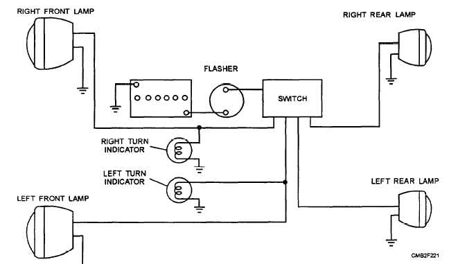
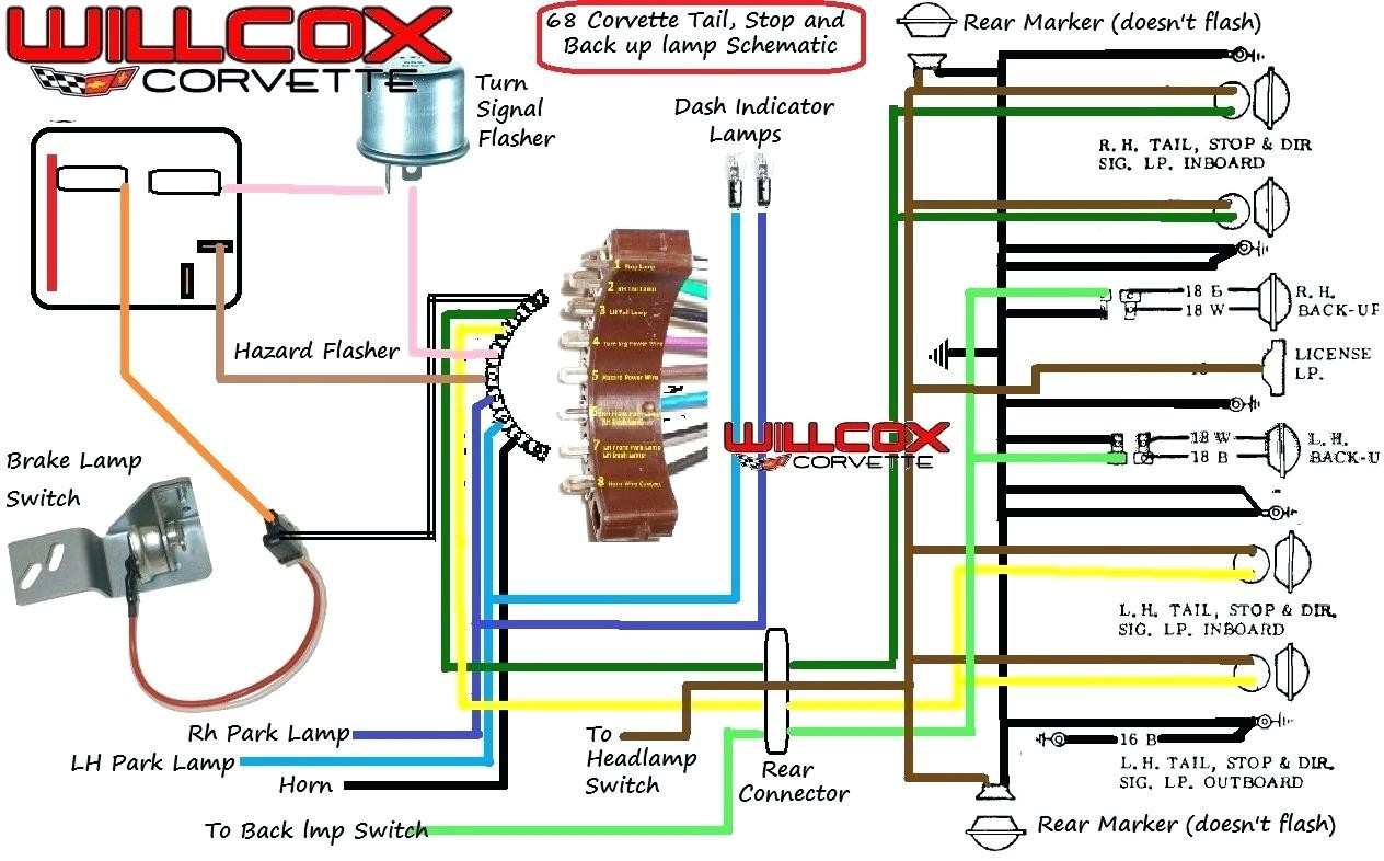
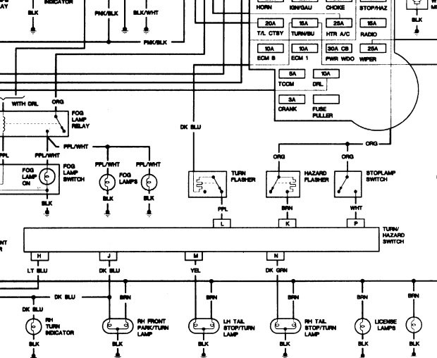
Blinker wiring diagram. Variety of universal turn signal wiring diagram. They will combine the brake wiring and the turn signal wiring so they will work. It shows the parts of the circuit as simplified forms and also the power and also signal links in between the devices. Wiring diagram motorcycle part 2 duration. It includes instructions and diagrams for various kinds of wiring strategies and other things like lights home windows and so on. The power goes through a fuse panel into the thermal flasher.
Turn signal flasher wiring diagram led turn signal flasher wiring diagram motorcycle turn signal flasher wiring diagram turn signal flasher circuit diagram every electric arrangement consists of various unique parts. You can get them at places like napa or here. I had many responses and have collected them in the pages that follow. Turn signal flasher info and wiring mechanical 2 prong old style explained duration. A quick and cheap way that works just as good is a tail light wiring converter for trailers. Chris craft 109479 views.
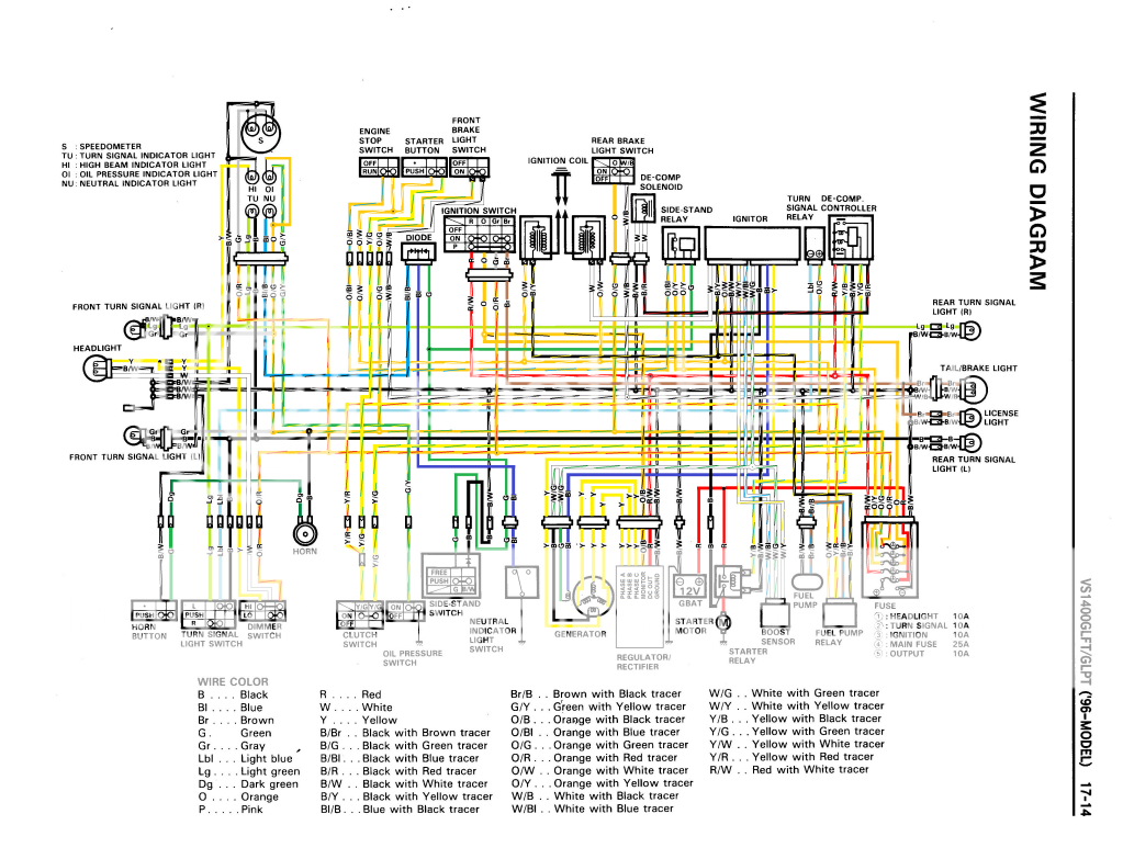
A wiring diagram is a streamlined standard pictorial depiction of an electric circuit. Unfortunately i didnt retain the sources. Some have the tail light wire running through them 4 wire into 3 wire and some dont 3 wire into 2 wire. Flashers and hazards turn signal flasher wiring diagram. Wiring diagram contains numerous comprehensive illustrations that display the link of varied products. A wiring diagram is a simplified conventional photographic depiction of an electric circuit.
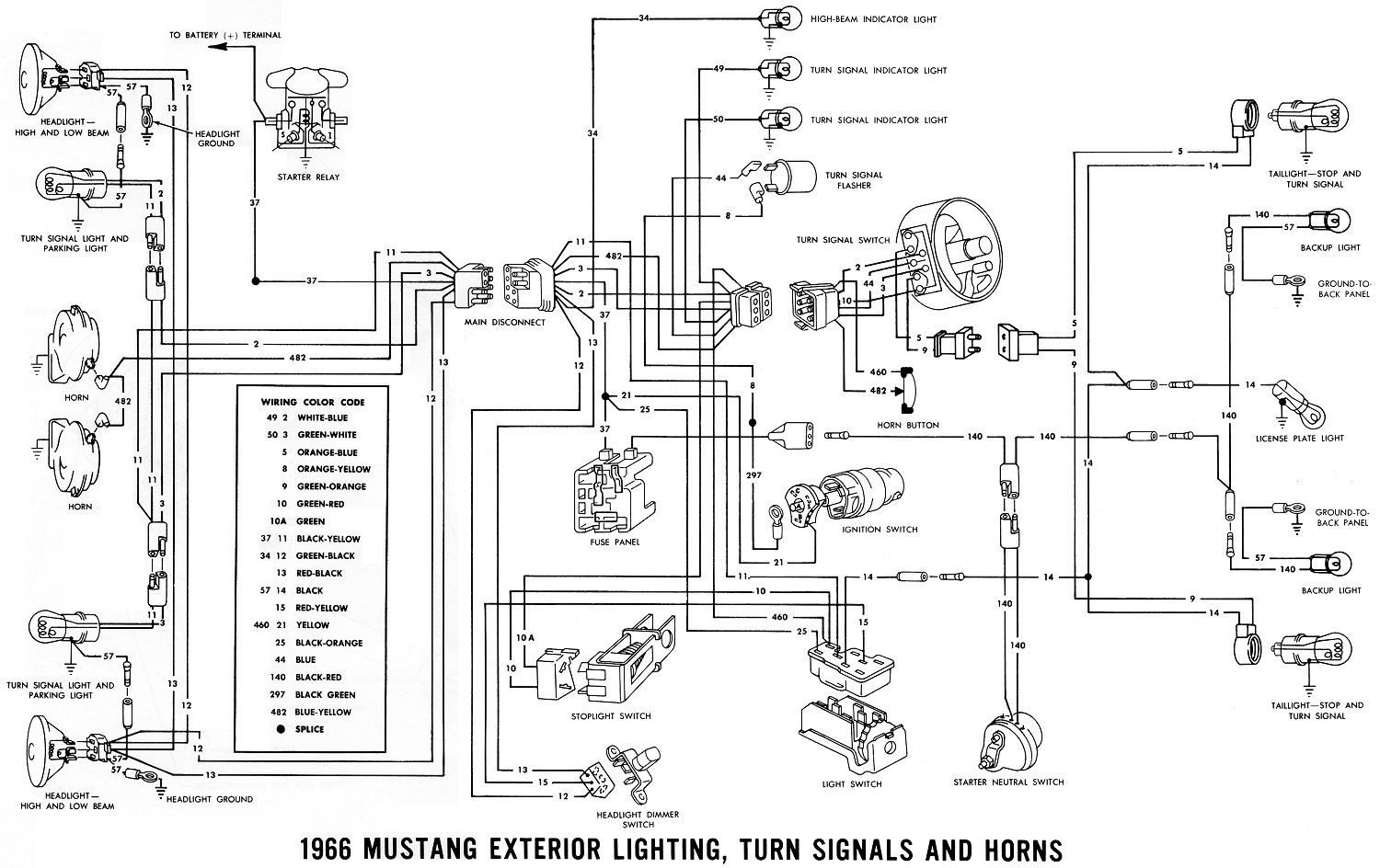
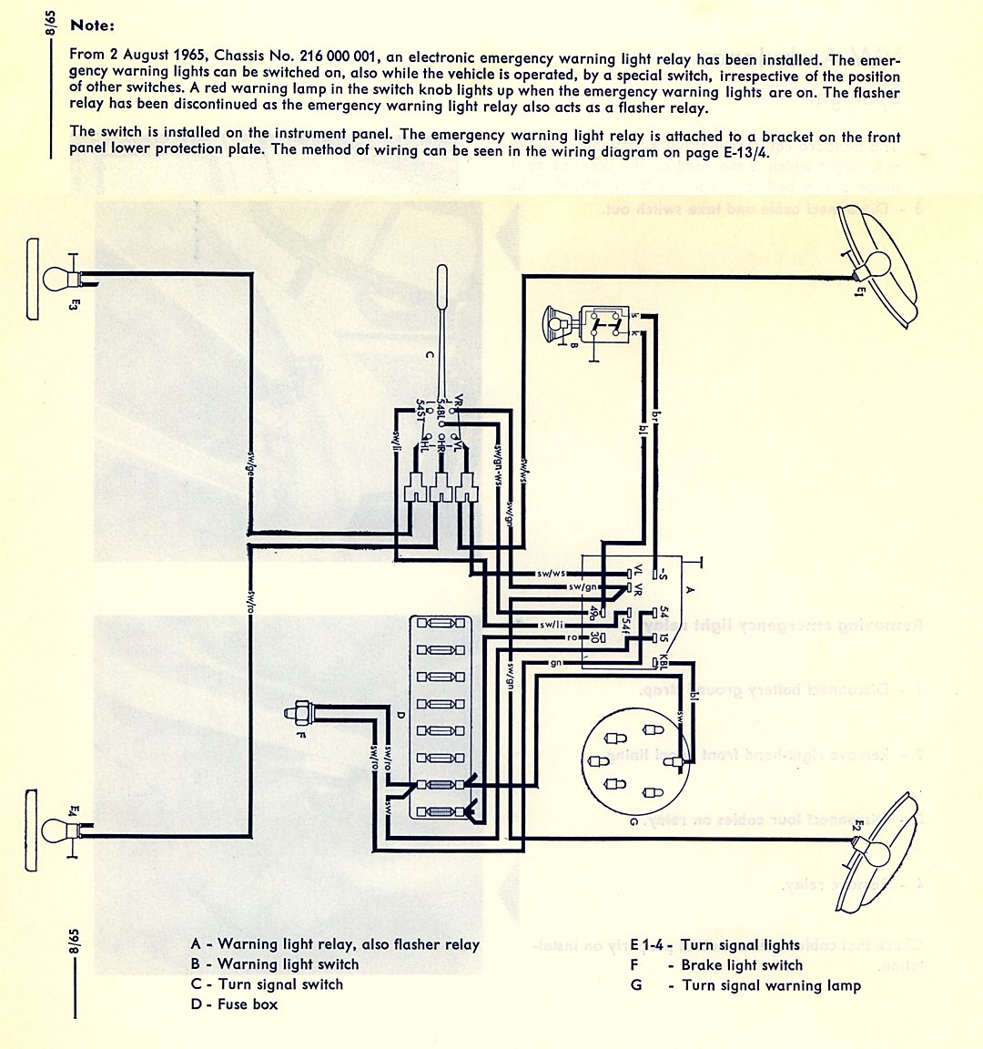
It reveals the elements of the circuit as streamlined forms and the power and also signal links between the devices. In addition i browsed the net and found a few more. Turn signal wiring diagrams recently i asked on fordbarn if anyone had wiring diagrams for the particular turn signal system everlasting that i have mounted on my 29 tudor. The turn signal circuit gets power when the ignition key is on. From there it goes to the stalk on the steering column. Each part should be placed and linked to other parts in specific way.
They look like this. If not the structure wont work as it ought to be. Chris craft 109657 views. Lets take a look at how the turn signal circuit is hooked up.
Gallery of Blinker Wiring Diagram