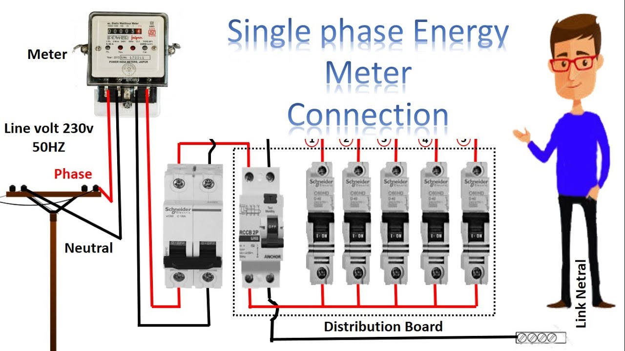
Following are the parts of the meter. It may be a bit difficult to see but the original meter base from the house is not changed.
Single Phase Meter Wiring Diagram Energy Meter Energy Meter Connection By Earthbondhon
Bidirectional meter wiring diagram. This is a simple and easy to construct circuit that can be used to provide a bidirectional drive to a dc motor. This guide is the basic reference tool for all onicon fb 3500 bi directional electromagnetic flow meters. Because of this i thought i would post up this solar metering wiring diagram for a simple solar metering installation. Part 1 farmcraft101 solar. Watch before you buy. Utility meters are bi directionalnet amr meter type and utility owned.
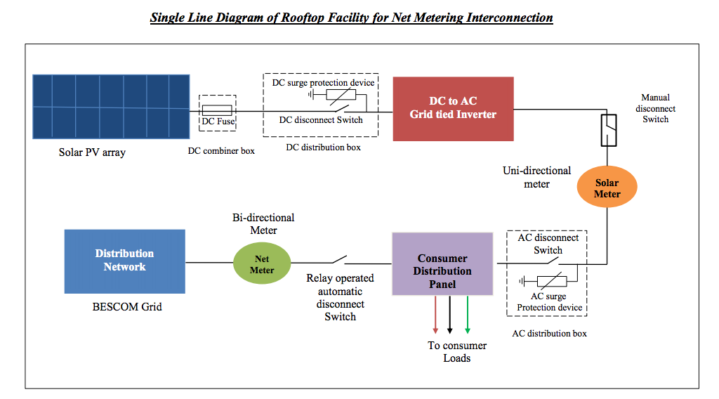
01 shows front view of a single phase solar bi directional meter. The following is a basic explanation of how bi directional metering works. If you have not purchased all of the options there will be references in this manual which are not applicable to your meters. Fb 3500 bi directional insertion electromagnetic flow meter manual 1215 0718 5 page 5. The circuit operation is straight forward. The ugly truth behind grid tie solar systems.
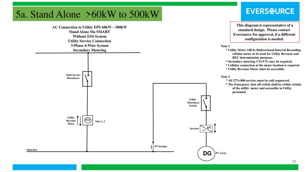
Output of an astable mutivibrator based on ic1 ne555 is used to control the relay rl1 driving the motor. Meter locations determined by utility for service access requirements. The wiring diagrams within this document represent standard conceptual designs for commonly used service installations. Bi directional metering is available to customers who install renewable fuel generators such as solar wind hydro or biomass sources and operate the generator in parallel with their electric companys electrical system. The most common way to do this is to install a trough either above or below the meter base to make the connections in. Electrical information of the meter is displayed on the name plate such as the type of connection voltage current frequency etc.
Gallery of Bidirectional Meter Wiring Diagram