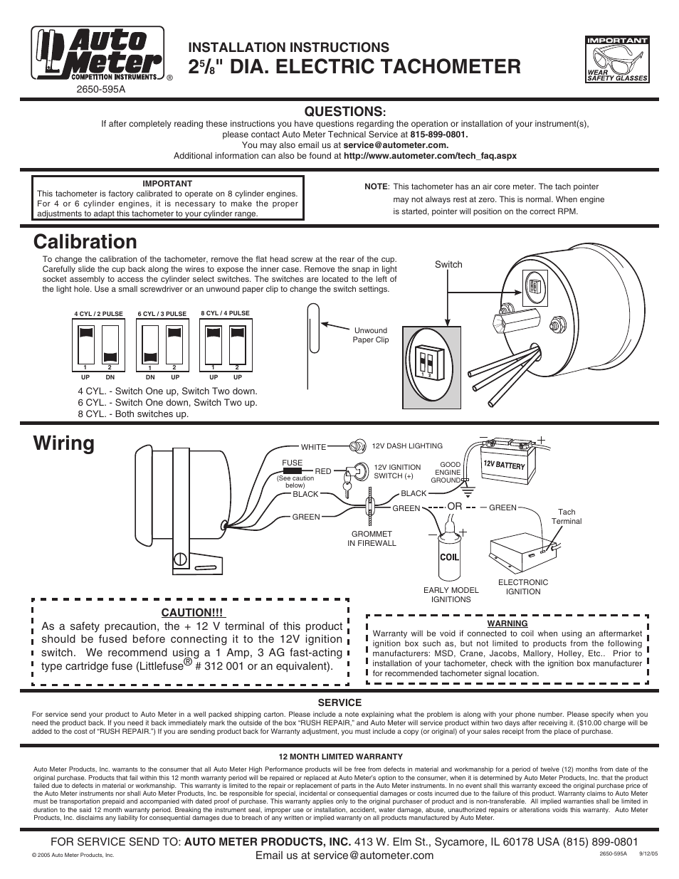
Diagram illustration on the right. It reveals the components of the circuit as simplified shapes and also the power and also signal connections in between the devices.

Best Rated In Automotive Performance Tachometers Amp Helpful
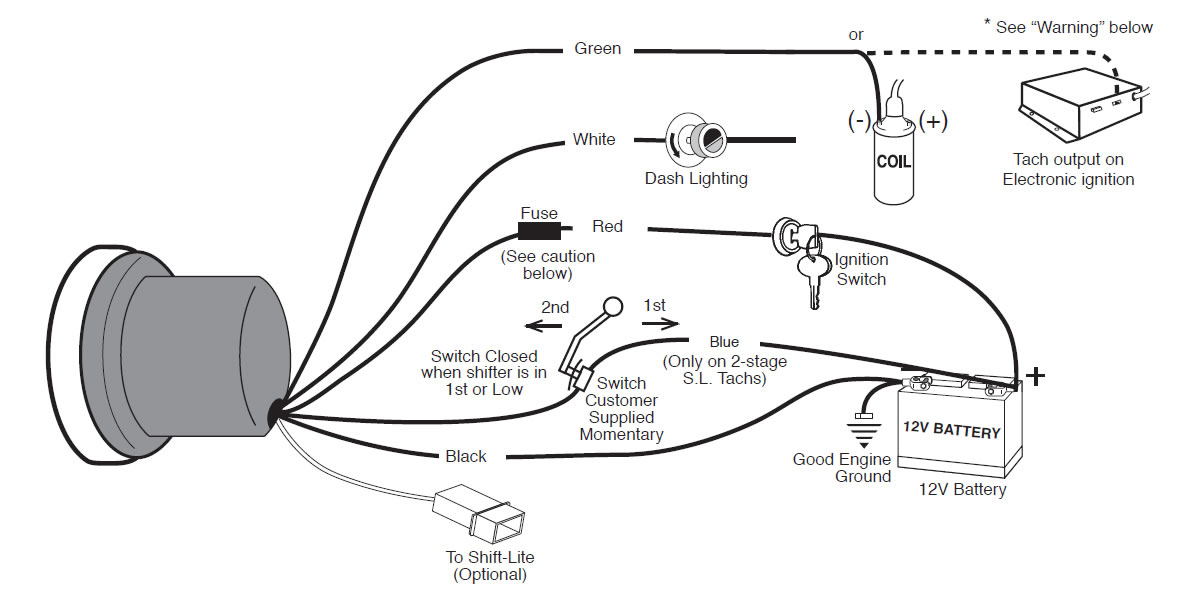
Autometer phantom tach wiring diagram. Gage model 2302 tachometer when used with auto meter model 5215 beilaser adapter. However it does not imply connection between the wires. It shows the components of the circuit as simplified shapes and the facility and signal connections along with the devices. The tachometer is designed to show the engine rpms or rotations per minute. Autometer phantom tach wiring diagram wiring diagram is a simplified satisfactory pictorial representation of an electrical circuit. Injunction of two wires is usually indicated by black dot on the junction of 2 lines.
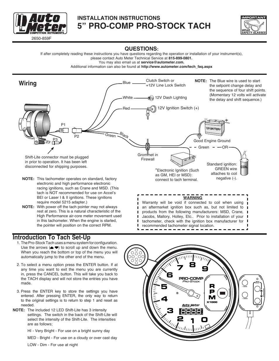
If after completely reading these instructions you have questions regarding the operation or installation of your instruments please contact auto meter technical service at 866 248 6357. Warrants to the consumer that all auto meter high performance products will be free from defects in material and workmanship for a period of twelve 12 months from date of the. Wiring your new autometer tachometer into your car will complete the installation. Laser ii with date code of 8100 or higher do not require adapter and use figure b for hook up. At times the wires will cross. Autometer has designed their tach to be used with four six.
Auto meter products inc. Variety of autometer tach wiring diagram. Once you have selected a mounting location you can run the four wires that operate the tachometer. As stated earlier the lines in a autometer tach wiring diagram represents wires. 5 tachometer 2650 1244 00 rev. A wiring diagram is a streamlined standard pictorial representation of an electrical circuit.
See diagram 1 if your terminal arrangement differs from one shown. Switch 2 up 8 cyl both switches up. 4 cyl both switches down 6 cyl switch 1 down. See diagram 1 if.
Gallery of Autometer Phantom Tach Wiring Diagram